CAMBIUM NETWORKS
026v003
49
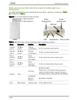
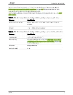
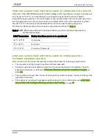
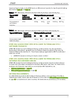
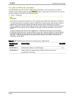
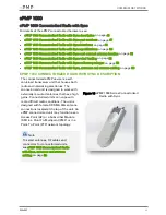
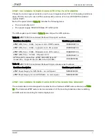
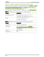
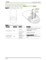
Table 13 ePMP 1000 Connectorized Radio with Sync interfaces
Name
Connector
Interface
Description
Antenna
port H
RP-SMA,
female
Antenna,
H polarization
To/from H polarized antenna port
Antenna
port V
RP-SMA,
female
Antenna,
V polarization
To/from V polarized antenna port
Ethernet
RJ45
PoE input
802.3af PoE Standard, as well as Proprietary
power over Ethernet (PoE) twisted pair (for
powering via CMM3/CMM4)
10/100/1000
Base-TX
Ethernet
Management and data
GPS
SMA, female
Antenna, GPS
To/from GPS antenna
Reset
Button
Physical button N/A
For resetting the radio and for setting the radio
back to its factory default configuration. See
Using the device external reset button
EPMP 1000
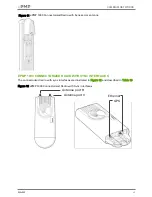
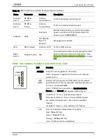
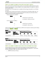
CONNECTORIZED RADIO WITH SYNC LEDS
LED
Function
POWER
Green: Power is applied to the device
Unlit: No power is applied to the device or improper
power source
GPS
SYNC
Orange: AP has acquired a 1PPS GPS synchronization
pulse either from the internal GPS module and antenna
or from a connected CMM
Unlit: 1PPS GPS not acquired, or Synchronization
Source set to Internal (AP operates without sync)
No LEDs lit: Three or less satellites tracked
One LED lit (bottom): Four or five satellites tracked
Two LEDs lit (bottom two): Six or seven satellites
tracked
All LEDs lit: Eight or more satellites are tracked
ETH
Once lit, blinking indicates Ethernet activity
Red: 10BaseTX link
Green: 100BaseTX link
Orange: 1000BaseTX link
Unlit: No Ethernet link established
Summary of Contents for ePMP
Page 198: ...CAMBIUM NETWORKS 026v003 198 Figure 61 SM Radio page Standard WiFi mode ...
Page 230: ...CAMBIUM NETWORKS 026v003 230 Figure 66 SM Network page Router mode ...
Page 466: ...CAMBIUM NETWORKS 026v003 466 ...
Page 467: ...CAMBIUM NETWORKS 026v003 467 ...
Page 468: ...CAMBIUM NETWORKS 026v003 468 Figure 87 FCC and IC certifications on 2 4 GHz product labels ...

