Chapter 2: System hardware
107
Sup p or t ed ext er nal A P ant ennas
The recommended AP external antennas are listed in List of AP external antennas .
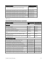
Table 81 :List of AP external antennas
Cambium description
Cambium part number
900 MHz 13 dBi 65 degree Sector Antenna (Dual Slant)
N009045D001A
5 GHz Horizontal and Vertical Polarization Antenna for 90 Degree Sector
85009324001
5 GHz Horizontal and Vertical Polarization Antenna for 60 Degree Sector
85009325001
Note
LINKPlanner, Cambium Networks, planning tool, contains an up- to- date,
exhaustive list of antennas that can be used with Cambium Products.
Sup p or t ed ext er nal BH/ SM ant enna
The recommended PTP 450i Series BH or PMP 450/450i Series SM external antenna is listed in PTP 450i
Series BH or PMP 450/450i Series SM external antenna.
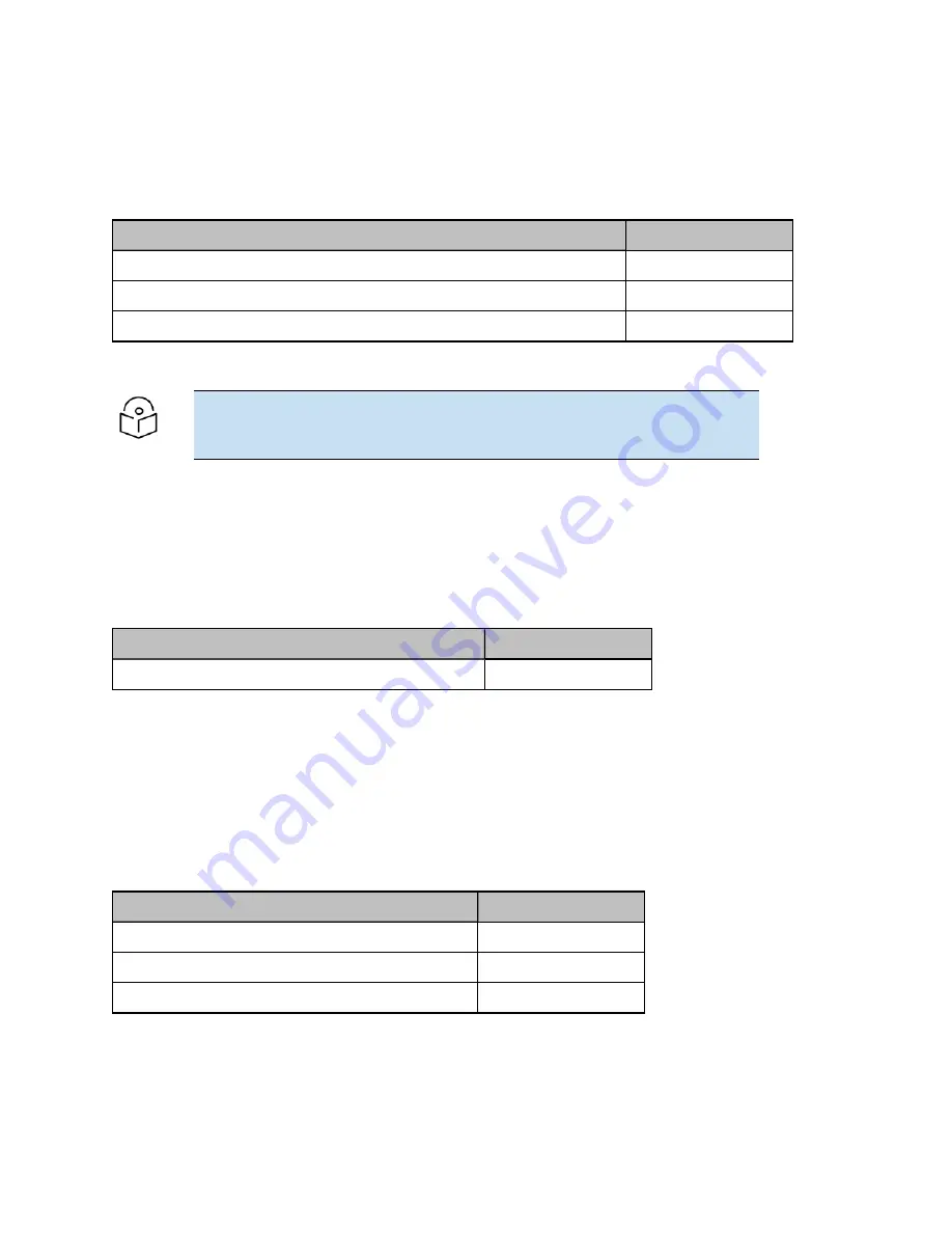
Table 82 :PTP 450i Series BH or PMP 450/450i Series SM external antenna
Cambium description
Cambium part number
900 MHz 12 dBi gain directional antenna (Dual Slant)
N009045D003A
RF cab le and connect or s
RF cable of generic type LMR-400 is required for connecting the ODU to the antenna. N type male
connectors are required for connecting the RF cables to the connectorized ODU. Two connectors are
required per ODU. Use weatherproof connectors, preferably ones that are supplied with adhesive lined
heat shrink sleeves that are fitted over the interface between the cable and connector. Order CNT-400 RF
cable and N type male connectors from Cambium Networks (RF cable and connector part numbers).
Table 83 :RF cable and connector part numbers
Cambium description
Cambium part number
50 Ohm Braided Coaxial Cable - 75 meter
30010194001
50 Ohm Braided Coaxial Cable - 500 meter
30010195001
RF Connector, N, Male, Straight for CNT-400 Cable
09010091001
A nt enna accessor ies
Connectorized ODUs require the following additional components:
Summary of Contents for PMP 450 Series
Page 92: ...Chapter 2 System hardware 92 Figure 29 MicroPoP Omni antenna implementation pattern Vertical...
Page 134: ...Chapter 3 System planning 134 Figure 51 Mast or tower installation...
Page 135: ...Chapter 3 System planning 135 Figure 52 Wall installation...
Page 136: ...Chapter 3 System planning 136 Figure 53 Roof installation...
Page 137: ...Chapter 3 System planning 137 Figure 54 GPS receiver wall installation...
Page 158: ...Chapter 3 System planning 158 Figure 61 cnMedusa Antenna...

