Chapter 2: System hardware
128
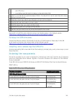
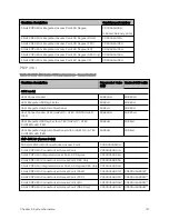
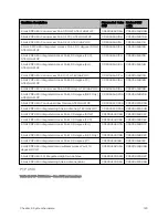
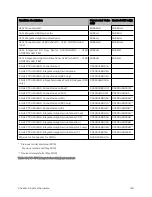
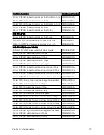
Cambium description
Cambium part number
3.6 GHz PMP 450 Subscriber Module, 20 Mbps
C036045C003A
3.6 GHz PMP 450 Subscriber Module, Uncapped
C036045C004A
3.6 GHz PMP 450 Connectorized Subscriber Module, 4 Mbps
C036045C005A
3.6 GHz PMP 450 Connectorized Subscriber Module, 10 Mbps
C036045C006A
3.6 GHz PMP 450 Connectorized Subscriber Module, 20 Mbps
C036045C007A
3.6 GHz PMP 450 Connectorized Subscriber Module, Uncapped
C036045C008A
5 GHz PMP 450 Integrated Subscriber Module, 4 Mbps
C054045C001B
5 GHz PMP 450 Integrated Subscriber Module, 10 Mbps
C054045C002B
5 GHz PMP 450 Integrated Subscriber Module, 20 Mbps
C054045C003B
5 GHz PMP 450 Integrated Subscriber Module, Uncapped
C054045C004B
5 GHz PMP 450 Connectorized Subscriber Module, 4 Mbps
C054045C005B
5 GHz PMP 450 Connectorized Subscriber Module, 10 Mbps
C054045C006B
5 GHz PMP 450 Connectorized Subscriber Module, 20 Mbps
C054045C007B
5 GHz PMP 450 Connectorized Subscriber Module, Uncapped
C054045C008B
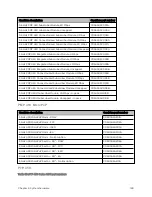
5 GHz PMP 450d Subscriber Module, 20 Mbps – 4-pack
C054045H013B
5 GHz PMP 450d Subscriber Module, Uncapped – 4-pack
C054045H014B
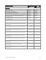
PMP 4 50 MicroPoP
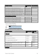
Cambium description
Cambium part number
5 GHz 450 MicroPoP Omni - ROW
C050045A201A
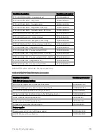
5 GHz 450 MicroPoP Omni - FCC
C050045A202A
5 GHz 450 MicroPoP Omni - ISED
C050045A203A
5 GHz 450 MicroPoP Omni - EU
C050045A204A
5 GHz 450 MicroPoP Omni - No Encription
C050045A205A
5 GHz 450 MicroPoP Sector - 90° - ROW
C050045A206A
5 GHz 450 MicroPoP Sector - 90° - FCC
C050045A207A
5 GHz 450 MicroPoP Sector - 90° - ISED
C050045A208A
5 GHz 450 MicroPoP Sector - 90° - EU
C050045A209A
5 GHz 450 MicroPoP Sector - 90° - No Encription
C050045A210A
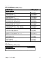
PTP 4 50
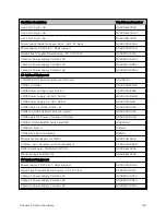
Table 96 :PTP 450 Series ODU part numbers
Summary of Contents for PMP 450 Series
Page 92: ...Chapter 2 System hardware 92 Figure 29 MicroPoP Omni antenna implementation pattern Vertical...
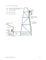
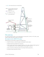
Page 134: ...Chapter 3 System planning 134 Figure 51 Mast or tower installation...
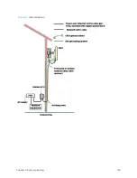
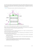
Page 135: ...Chapter 3 System planning 135 Figure 52 Wall installation...
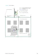
Page 136: ...Chapter 3 System planning 136 Figure 53 Roof installation...
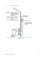
Page 137: ...Chapter 3 System planning 137 Figure 54 GPS receiver wall installation...
Page 158: ...Chapter 3 System planning 158 Figure 61 cnMedusa Antenna...

