Chapter 3: System planning
142
l
Up to 200 mph (Connectorized) for PMP/PTP 450i – all models 3 GHz and 5 GHz
l
Up to 200 mph (322 kph) for PMP/PTP 450 – all models
l
Up to 200 mph (322 kph) for PMP 450 – Ruggedized
l
Up to 200 mph (322 kph) for PMP 450i – all models 900 MHz
l
Up to 118 mph (191 kph) for PMP 450b Mid-Gain
l
Up to 90 mph (145 kph) for PMP 450b High Gain
l
Up to 90 mph (145 kph) for PMP 450d
l
Up to 100 mph (161 kph) for 900 MHz antennas
l
Up to 124 mph (200 kph) for PMP 450 MicroPoP Series - AP 5 GHz
l
Up to 124 mph (200 kph) for PMP/PTP 450b Retro Series - 5 GHz
Wind blowing on the ODU will subject the mounting structure to significant lateral force. The magnitude of
the force depends on both wind strength and surface area of the ODU. Wind loading is estimated using the
following formulae:
l
Force (in kilograms) = 0.1045aV
2
where:
l
“a” is the surface area in square meters, and “V” is the wind speed in meters per second.
l
Force (in pounds) = 0.0042Av
2
l
where:
o
“A” is the surface area in square feet, and
o
“v” is the wind speed in miles per hour.
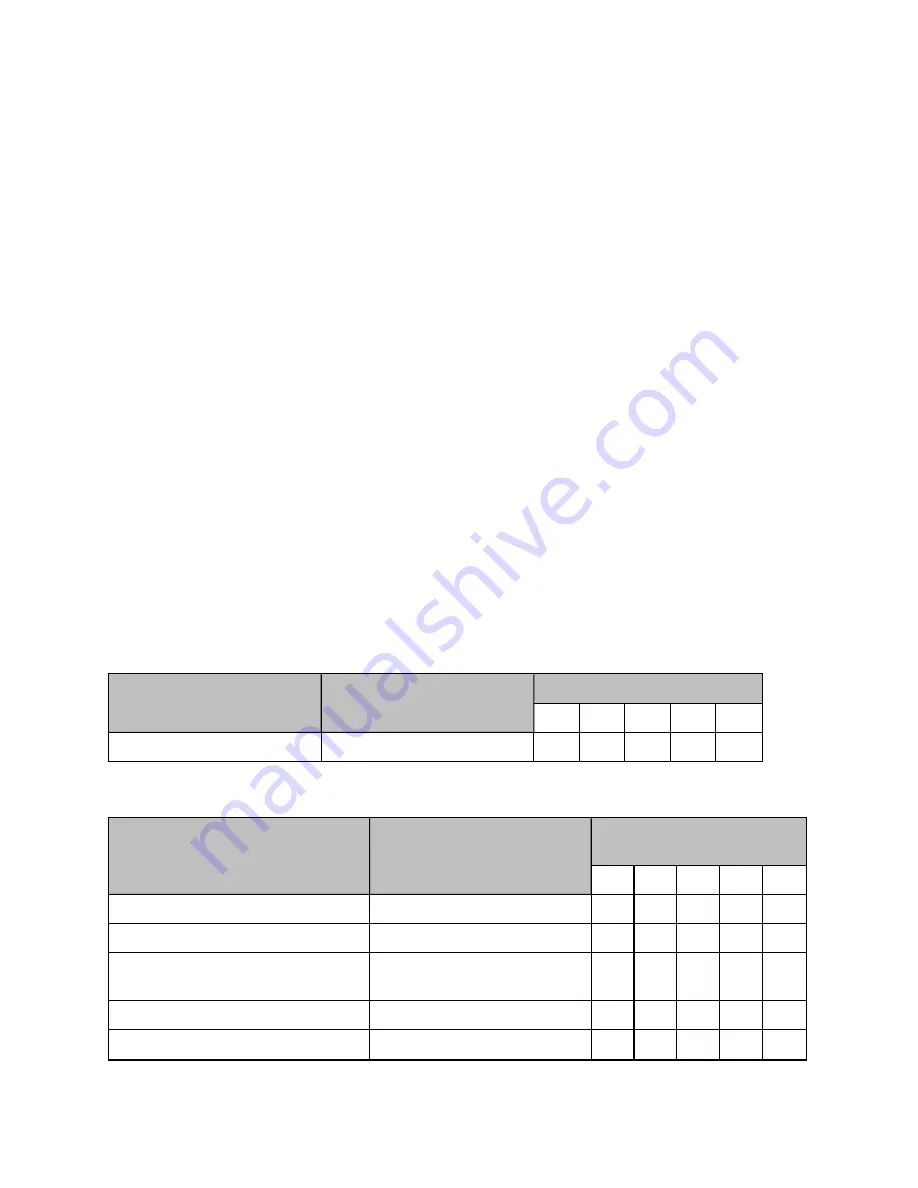
Applying these formulae to the 450 platform at different wind speeds, the resulting wind loadings are
shown in below tables.
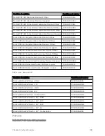
Table 98 :PMP 450m Series wind loading (Newton)
Type of ODU
Max surface area (square feet)
Wind speed (kilometer per hour)
160
170
180
190
200
Integrated 90º sector antenna
0.331
671
757
849
946
1048
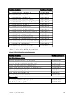
Table 99 :PMP/PTP 450i Series wind loading (Newton)
Type of ODU
Max surface area (square
meters)
Wind speed (kilometer per
hour)
160
170
180
190
200
Connectorized
0.035
94
106
119
132
146
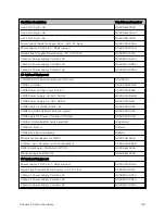
Directional Yagi antenna - 900 MHz
0.025
67
76
85
94
105
External 65º sector antenna – 900
MHz
0.253
677
764
857
954
1058
Directional antenna – 3.x GHz
0.1
142
160
180
200
222
Integrated 90º sector antenna - 3.x
0.18
83
94
105
117
130
Summary of Contents for PMP 450 Series
Page 92: ...Chapter 2 System hardware 92 Figure 29 MicroPoP Omni antenna implementation pattern Vertical...
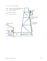
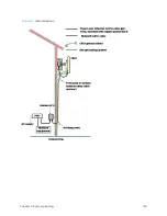
Page 134: ...Chapter 3 System planning 134 Figure 51 Mast or tower installation...
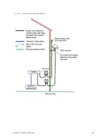
Page 135: ...Chapter 3 System planning 135 Figure 52 Wall installation...
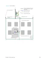
Page 136: ...Chapter 3 System planning 136 Figure 53 Roof installation...
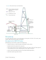
Page 137: ...Chapter 3 System planning 137 Figure 54 GPS receiver wall installation...
Page 158: ...Chapter 3 System planning 158 Figure 61 cnMedusa Antenna...

