Chapter 3: System planning
145
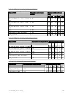
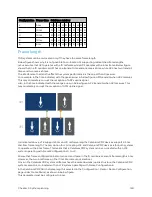
Table 105 :PMP 450b Series wind loading (lb force)
Type of ODU
Max surface area (square feet)
Wind speed (miles per hour)
100
105
110
115
120
Integrated Mid-Gain
0.33
13
15
16
18
19
Integrated High Gain
1.41
59
65
71
78
85
Hazard o us lo cat io ns
Check that the ODUs will not be exposed to hazardous gases, as defined by HAZLOC (USA) and ATEX
(Europe) regulations. If there is a risk of such exposure, then order the PTP/PMP 450i ATEX/Hazloc
product variants, as these are intended for operation in locations with gas hazards. The ATEX and
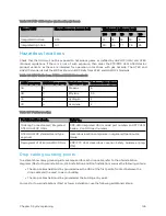
HAZLOC standards limit the EIRP as shown in EIRP limits from ATEX and HAZLOC standards.
Table 106 :EIRP limits from ATEX and HAZLOC standards
ATEX gas group
HAZLOC gas group
Typical gas type
Maximum EIRP (Watt)
IIA
D
Propane
6
IIB
C
Ethylene
3.5
IIC
B
Hydrogen
2
IIC
A
Acetylene
2
Table 107 :Further reading
For information about…
Refer to…
Ordering Connectorized/ Integrated
ATEX/HAZLOC ODUs
PMP 450i Integrated ODU models/part numbers and PTP 450i
Series – Con ODU part numbers
ATEX/HAZLOC standards and type
approval
Hazardous location compliance in Legal and Open Source
Guide.
Deployment of ATEX/HAZLOC ODUs
PMP/PTP 450i Hazardous Location Safety Guidance (pmp-
1712)
Dr op cab le g r ound ing p oint s
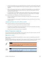
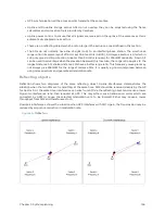
To estimate how many grounding kits are required for each drop cable, refer to the site installation
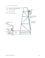
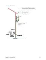
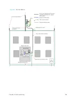
diagrams (Mast or tower installation , Wall installation, and Roof installation) and use the following criteria:
l
The drop cable shield must be grounded near the ODU at the first point of contact between the
drop cable and the mast, tower or building.
l
The drop cable shield must be grounded at the building entry point.
For mast or tower installations (Mast or tower installation), use the following additional criteria:
Summary of Contents for PMP 450 Series
Page 92: ...Chapter 2 System hardware 92 Figure 29 MicroPoP Omni antenna implementation pattern Vertical...
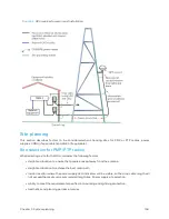
Page 134: ...Chapter 3 System planning 134 Figure 51 Mast or tower installation...
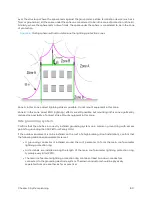
Page 135: ...Chapter 3 System planning 135 Figure 52 Wall installation...
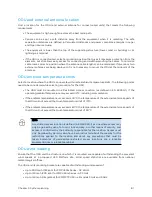
Page 136: ...Chapter 3 System planning 136 Figure 53 Roof installation...
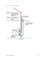
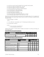
Page 137: ...Chapter 3 System planning 137 Figure 54 GPS receiver wall installation...
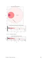
Page 158: ...Chapter 3 System planning 158 Figure 61 cnMedusa Antenna...


