Chapter 3: System planning
156
l
GPS synchronization: all the access points transmit at the same time
l
Uplink and Downlink timings across APs do not overlap: they can be adjusted using the frame
calculators and co-location tools provided by Cambium
l
Uplink power control to ensure that all signals are received on the uplink at the same level: this is
automatically enabled on all sectors
l
There are no reflecting objects which are too large in the exclusion zones defined in this section.
l
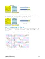
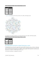
The SMs do not normally have line-of-sight (LoS) to an interfering base station. The worst-case
range ratio in Example layout of 16 Access Point sectors (ABCD), 90-degree sectors is 5:1 which in
LoS only gives 14 dB protection. Greater than 30 dB is required for 256QAM capability. Down tilt
can be used to advantage when the elevation beamwidth is low. Also, the range ratio applies to the
longest distance SM, shorter distance SMs have a better range ratio. This frequency reuse plan may
not always give 256QAM for the longest distance SMs. It is usually a good compromise between
using more spectrum and guaranteed modulation rate.
Reflect ing object s
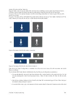
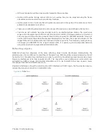
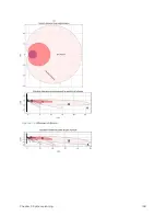
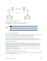
Reflection shows two diagrams of the same reflecting object. Uplink interference demonstrates the
situation when the two SMs are transmitting at the same time. SM2 should be received cleanly by the AP
for Sector 3. At the same time interference can arise from SM1 via the reflecting object and cause a lower
Signal- to- Interference ratio than required at AP3. This may either cause transmission errors which are
corrected by ARQ or cause the selected modulation rate to be lowered. Either may cause a lower
throughput from SM2 and therefore sector 3.
Downlink interference shows the situation when AP3 interferes with SM1. Again, the transmission may be
reduced by errors or a reduction in modulation rate.
Figure 59 :
Reflection
Summary of Contents for PMP 450 Series
Page 92: ...Chapter 2 System hardware 92 Figure 29 MicroPoP Omni antenna implementation pattern Vertical...
Page 134: ...Chapter 3 System planning 134 Figure 51 Mast or tower installation...
Page 135: ...Chapter 3 System planning 135 Figure 52 Wall installation...
Page 136: ...Chapter 3 System planning 136 Figure 53 Roof installation...
Page 137: ...Chapter 3 System planning 137 Figure 54 GPS receiver wall installation...
Page 158: ...Chapter 3 System planning 158 Figure 61 cnMedusa Antenna...

