Chapter 3: System planning
160
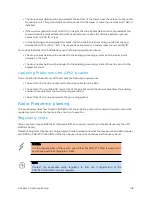
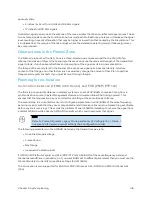
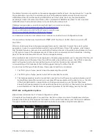
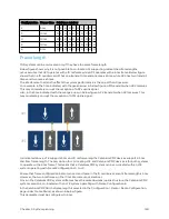
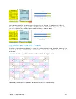
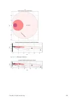
Figure 62 :
PMP 450m Series AP antenna beam
PMP 4 50 m inst allat ion recommendat ions
l
For best performance it is recommended to have a clearance zone around the mast. The clearance
zone depends on the surrounding environment and the antenna’s down tilt. If the mast is
surrounded by metal, then larger clearance is required compared to an environment where the
antenna is surrounded by foliage
l
SMs should be spread in azimuth of AP antenna
l
450m is susceptible to movement, for best MU- MIMO performance it is recommended that the
450m AP is mounted/installed on a mast that is extremely rigid (no movement and is vertical).
l
LINKPlanner can be used to plan SMs across the AP antenna azimuth
Link p lanning
This section describes factors to be considered when planning links, such as range, obstacles path loss and
throughput. LINKPlanner is recommended.
Rang e and ob st acles
Calculate the range of the link and identify any obstacles that may affect radio performance.
Perform a survey to identify all the obstructions (such as trees or buildings) in the path and to assess the
risk of interference. This information is necessary in order to achieve an accurate link feasibility
assessment.
Summary of Contents for PMP 450 Series
Page 92: ...Chapter 2 System hardware 92 Figure 29 MicroPoP Omni antenna implementation pattern Vertical...
Page 134: ...Chapter 3 System planning 134 Figure 51 Mast or tower installation...
Page 135: ...Chapter 3 System planning 135 Figure 52 Wall installation...
Page 136: ...Chapter 3 System planning 136 Figure 53 Roof installation...
Page 137: ...Chapter 3 System planning 137 Figure 54 GPS receiver wall installation...
Page 158: ...Chapter 3 System planning 158 Figure 61 cnMedusa Antenna...

