Chapter 4: Preparing for installation
192
O DU diagnost ic LEDs
See section AP/BHM LEDs on page 1.
l
See section 5 GHz 450b BHM LED descriptions
LED
Color when active
Status
information
provided
Notes
POWER
Blue
DC power
Always lit after 10-20 seconds of power on.
SYNC
Green
Presence of
sync
-
SES
Yellow
Unused
-
GPS
Red
Pulse of sync
Lit when the BHM is getting a sync pulse from a GPS
source goes along with SYNC.
ETH
Red/Green/
Orange (multi-
colored for
10/100/1000).
Presence of
data activity
on the
Ethernet link
Lit when link is present: 10Base-T = Red 100Base-T =
Green 1000Base-T = Orange Flashes during data
transfer. Frequency of flash is not a diagnostic indication.
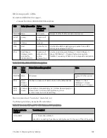
Table 116 :3 GHz 450b BHM LED descriptions
LED
Color
when
active
Status information provided
Note
POWER
Blue
DC power
Always lit after power
on
ETH
Red /
Green /
Orange
Flashes in presence of data activity on the Ethernet link
10Base-T = Red
100Base-T = Green
1000Base-T = Orange
SES/
SYN
Yellow /
Green
Sync status: - Generating sync = Yellow Receiving sync =
Green Solid = Unit transmitting Blinking = Unit
synchronized, but not transmitting
-
Recommended Tools for Inst allat ion
The following tools may be needed for installation:
Table 117 :Tools for PMP and PTP 450 Platform ODU installation
Equipment to Be
Installed
Tools Required
AP or BHM
l
3 mm Allen Wrench
Used for connecting the antenna mating bracket to the rear of the AP housing
Summary of Contents for PMP 450 Series
Page 92: ...Chapter 2 System hardware 92 Figure 29 MicroPoP Omni antenna implementation pattern Vertical...
Page 134: ...Chapter 3 System planning 134 Figure 51 Mast or tower installation...
Page 135: ...Chapter 3 System planning 135 Figure 52 Wall installation...
Page 136: ...Chapter 3 System planning 136 Figure 53 Roof installation...
Page 137: ...Chapter 3 System planning 137 Figure 54 GPS receiver wall installation...
Page 158: ...Chapter 3 System planning 158 Figure 61 cnMedusa Antenna...


