Chapter 4: Preparing for installation
194
Best Pract ices for Cabling
The following practices are essential to the reliability and longevity of cabled connections:
l
Use only shielded cables to resist interference.
l
For vertical runs, provide cable support and strain relief.
l
Include a 2-ft (0.6-m) service loop on each end of the cable to allow for thermal expansion and
contraction and to facilitate terminating the cable again when needed.
l
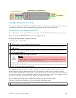
Include a drip loop to shed water so that most of the water does not reach the connector at the
device.
l
Properly crimp all connectors.
l
Use dielectric grease on all connectors to resist corrosion.
l
Use only shielded connectors to resist interference and corrosion.
W iring Connect ors
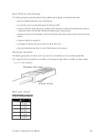
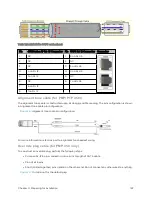
The following diagrams correlate pins to wire colors and illustrate crossovers where applicable.
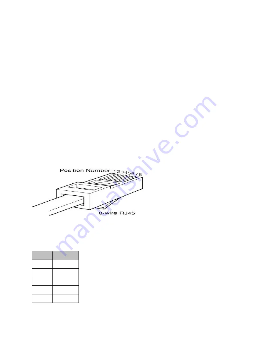
Pin 1, relative to the lock tab on the connector of a straight-through cable is located as shown below.
Figure 74 :
Pin 1 location
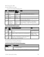
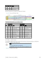
Main port pinout
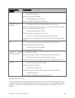
Table 118 : Main port pinout
RJ45 pin Description
1
+TxRx0
2
–TxRx0
3
+TxRx1
4
+TxRx2
5
–TxRx2
Summary of Contents for PMP 450 Series
Page 92: ...Chapter 2 System hardware 92 Figure 29 MicroPoP Omni antenna implementation pattern Vertical...
Page 134: ...Chapter 3 System planning 134 Figure 51 Mast or tower installation...
Page 135: ...Chapter 3 System planning 135 Figure 52 Wall installation...
Page 136: ...Chapter 3 System planning 136 Figure 53 Roof installation...
Page 137: ...Chapter 3 System planning 137 Figure 54 GPS receiver wall installation...
Page 158: ...Chapter 3 System planning 158 Figure 61 cnMedusa Antenna...

