Chapter 5: Installation
224
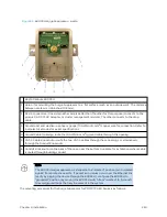
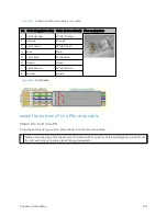
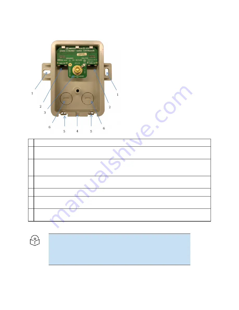
Figure 82 :
600SSH Surge Suppressor – inside
Key to Callouts 600SSH
1
Holes—for mounting the Surge Suppressor to a flat surface (such as an outside wall). The distance
between centers is 4.25 inches (108 mm).
2
RJ-45 connectors—One side (neither side is better than the other for this purpose) connects to the
product (AP, SM, AC Adapter, or cluster management module). The other connects to the drop
cable.
3
Ground post and washer—use heavy gauge (10 AWG or 6 mm
2
) copper wire for connection. Refer to
local electrical codes for exact specifications.
4
Ground Cable Opening—route the 10 AWG (6 mm
2
) ground cable through this opening.
5
CAT-5 Cable Knockouts—route the two CAT-5 cables through these openings, or alternatively
through the Conduit Knockouts.
6
Conduit Knockouts—on the back of the case, near the bottom. Available for installations where cable
is routed through building conduit.
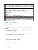
Note
The 600SSH surge suppressor is shipped in the “isolated” position (pin 4 isolated
by 68V from protective earth). If packet error issues occur over the Ethernet link
(verify by pinging the device through the 600SSH), configure the 600SSH to
“grounded” position (by moving the 600SSH switch from “isolated” to “ground”)
to avoid ground loops that may be present in the system.
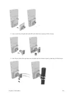
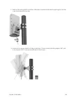
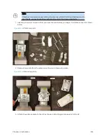
The mounting procedure for the Surge Suppressor for PMP/PTP 450 Series is as follows:
Summary of Contents for PMP 450 Series
Page 92: ...Chapter 2 System hardware 92 Figure 29 MicroPoP Omni antenna implementation pattern Vertical...
Page 134: ...Chapter 3 System planning 134 Figure 51 Mast or tower installation...
Page 135: ...Chapter 3 System planning 135 Figure 52 Wall installation...
Page 136: ...Chapter 3 System planning 136 Figure 53 Roof installation...
Page 137: ...Chapter 3 System planning 137 Figure 54 GPS receiver wall installation...
Page 158: ...Chapter 3 System planning 158 Figure 61 cnMedusa Antenna...

