Chapter 5: Installation
246
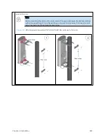
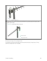
and tightening the (2) serrated flange nuts using a 13mm spanner wrench. These must be tightened
evenly on the pole to avoid jumping/stripping threads.
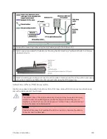
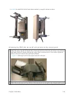
Figure 112 :
Attaching the AP antenna lower bracket to the pole
3
Use a local map, compass, and/or GPS device as needed to determine the direction that one or more
APs require to each cover the 90° sector.
4
Choose the best mounting location for your particular application.
Note
Use the embedded spectrum analyzer or a commercial analyzer to evaluate the
frequencies present in various locations. OFDM APs need not be mounted next to each
other. They can be distributed throughout a given site. However, the 90° offset must be
maintained. If you want to collocate these APs with PMP 100 Series APs of the 5.4-GHz
frequency band range, plan to allow at least 25 MHz of separation between their center
channels.
5
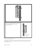
Secure a ground strap to the ground lug on the back of the AP.
6
Secure the ground strap to the pole, tower, or other trusted ground.
7
The bracket of the standard antenna has provision for measured down tilt. The recommended
practice is to use one of the many radio analysis and mapping tools or on-line tools to calculate down
tilt based on antenna height above the service area.
The proper angle of tilt can be calculated as a factor of both the difference in elevation and the
distance that the link spans. Even in this case, a plumb line and a protractor can be helpful to ensure
the proper tilt. This tilt is typically minimal.
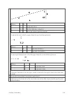
The number of degrees to offset (from vertical) the mounting hardware leg of the support tube is
equal to the angle of elevation from the lower module to the higher module (<B in the example
provided in Straight-through Ethernet Cable).
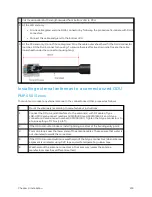
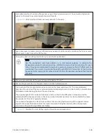
Figure 113 :
Variables for calculating angle of elevation (and depression)
Summary of Contents for PMP 450 Series
Page 92: ...Chapter 2 System hardware 92 Figure 29 MicroPoP Omni antenna implementation pattern Vertical...
Page 134: ...Chapter 3 System planning 134 Figure 51 Mast or tower installation...
Page 135: ...Chapter 3 System planning 135 Figure 52 Wall installation...
Page 136: ...Chapter 3 System planning 136 Figure 53 Roof installation...
Page 137: ...Chapter 3 System planning 137 Figure 54 GPS receiver wall installation...
Page 158: ...Chapter 3 System planning 158 Figure 61 cnMedusa Antenna...

