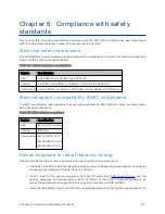
Chapter 6: Compliance with safety standards
279
Calculat ed d ist ances and p o w er co m p liance m arg ins
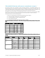
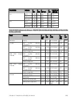
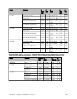
The following tables show calculated minimum separation distances, recommended distances and
resulting margins for each frequency band and antenna combination for the USA and Canada. These are
conservative distances that include compliance margins. At these and greater separation distances, the
power density from the RF field is below generally accepted limits for the general population.
450 Platform Family ODU adheres to all applicable EIRP limits for transmit power when operating in MIMO
mode. Separation distances and compliance margins include compensation for both transmitters.
Explanation of terms used in the following tables:
l
P burst – maximum average transmit power during transmit burst (Watt)
l
P – maximum average transmit power of the radio (Watt)
l
G – total transmit gain as a factor, converted from dB
l
S – power density (Watt/m2)
l
d – minimum safe separation distance from point source (meters)
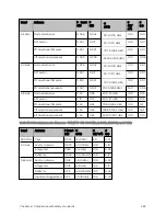
Table 126 :FCC minimum safe distances – PMP 450m 3 GHz and 5 GHz (5.1 GHz, 5.2 GHz, 5.4 GHz and 5.8
GHz)
Band (GHz)
Antenna
PG (W)
S (W/ m2)
d (m)
3.65
90° sector
33.9
10
0.52
4.9
90° sector
174
10
1.08
5.1
90° sector
3.38
10
0.16
5.2
90° sector
0.85
10
0.08
5.4
90° sector
0.85
10
0.08
5.8
90° sector
3.38
10
0.16
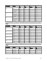
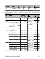
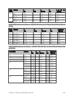
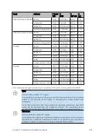
Table 127 :FCC minimum safe distances – PMP/PTP 450b 3.65 GHz, 4.9 GHz, 5.1 GHz, 5.2 GHz, 5.4 GHz and
5.8 GHz
Band (GHz)
Antenna
P
(W)
G
(dBi)
S
(W/ m2)
d
(m)
3.65
Dish
0.199
20.0
10.0
0.40
4.9
Dish
0.501
24.0
10.0
1.00
Patch Array
0.501
17.0
10.0
0.45
On-board
0.501
0
10.0
0.06
5.1
Dish
0.501
24.0
10.0
1.00
Patch Array
0.501
17.0
10.0.
0.45
On-board
0.501
0
10.0
0.06
Summary of Contents for PMP 450 Series
Page 92: ...Chapter 2 System hardware 92 Figure 29 MicroPoP Omni antenna implementation pattern Vertical...
Page 134: ...Chapter 3 System planning 134 Figure 51 Mast or tower installation...
Page 135: ...Chapter 3 System planning 135 Figure 52 Wall installation...
Page 136: ...Chapter 3 System planning 136 Figure 53 Roof installation...
Page 137: ...Chapter 3 System planning 137 Figure 54 GPS receiver wall installation...
Page 158: ...Chapter 3 System planning 158 Figure 61 cnMedusa Antenna...

