Chapter 1: Product description
28
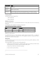
The 450b Series is supplied in the following configurations:
Table 6 :PMP/PTP 450b Series hardware configurations
ODU
Frequency
ODU type
Antenna Gain / Type
450b
3.3 to 3.9 GHz
High Gain
20 dBi Dish antenna
4.9 to 5.925 GHz
(supports 4.9, 5.1, 5.2, 5.4 and 5.8 GHz bands)
Mid-Gain
16 dBi integrated antenna
High Gain
23 dBi Dish antenna
PMP/ PTP 4 50 Series
Cambium PMP/PTP 450 Series networks are designed for wireless point-to-multipoint and point-to-point
links in the unlicensed/licensed 900 MHz, 2.4 GHz, 3.5 GHz, 3.65 GHz, 5.4 GHz and 5.8 GHz bands. Users
must ensure that the PMP/PTP 450 Series complies with local operating regulations.
The PMP/PTP 450 Series enables network operators to grow their business by offering more capacity for
data, voice and video applications.
Key features
The Cambium PMP/PTP 450 Series offers the following benefits:
l
Cambium’s point-to-multipoint and point-to-point solution, with up to 310 Mbps usable throughput
l
State-of-the-art MIMO (Multi In Multi Out) technology
l
Efficient GPS synchronized, scheduled TDD operation for easy Access Point site deployment and
performance that is consistent regardless of subscriber loading
l
A range of cost- effective subscriber device solutions to meet the business case of a network
application
l
MIMO- B Mode: This technique provides for the ability to double the throughput of a radio
transmission under proper RF conditions. Different data streams are transmitted simultaneously on
two different antennas.
l
MIMO- A Mode: This mode of operation using the same modulation levels as the MIMO- B mode,
namely: QPSK, 16-QAM, 64-QAM and 256-QAM but it provides an additional combining gain.
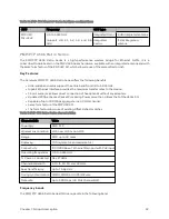
Below table gives a summary of PMP/PTP 450 Series products main characteristics.
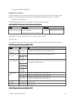
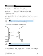
Table 7 :Main characteristics of the PMP/PTP 450 Series
Characteristic
Value
Topology
PMP/PTP
Wireless link condition
LOS, near LOS or non-LOS
Range
Up to 40 mi (or 64 km) for PMP
Up to 186 mi (or 299 km) for PTP
Summary of Contents for PMP 450 Series
Page 92: ...Chapter 2 System hardware 92 Figure 29 MicroPoP Omni antenna implementation pattern Vertical...
Page 134: ...Chapter 3 System planning 134 Figure 51 Mast or tower installation...
Page 135: ...Chapter 3 System planning 135 Figure 52 Wall installation...
Page 136: ...Chapter 3 System planning 136 Figure 53 Roof installation...
Page 137: ...Chapter 3 System planning 137 Figure 54 GPS receiver wall installation...
Page 158: ...Chapter 3 System planning 158 Figure 61 cnMedusa Antenna...


