Chapter 2: System hardware
64
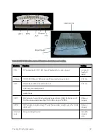
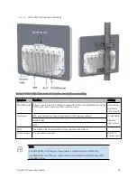
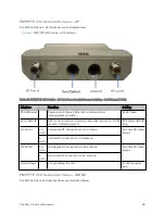
AP/ BHM LEDs
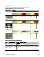
The diagnostic LEDs report the information about the status of the AP/BHM.
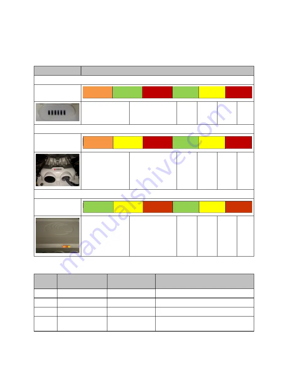
Table 35 :AP/BHM diagnostic LEDs, viewed from unit front
ODU LED Display
LED Labels
PMP 450m Series - AP
MAIN LNK+ACT/5
AUX LNK+ACT/4
GPS/3
SES/2
SYN/1
PWR
PMP/PTP 450i Series - AP/BHM
MAIN LNK/5
ACT/4
GPS/3
SES/2
SYN/1
PWR
PMP/PTP 450 Series - AP/BHM
MAIN LNK/5
ACT/4
GPS/3
SES/2
SYN/1
PWR
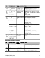
Table 36 :450m/450i/450 AP/BHM LED descriptions
LED
Color when active
Status
information
provided
Notes
PWR
Red
DC power
Always lit after 10-20 seconds of power on.
SYN/1
Yellow
Presence of sync
-
SES/2
Green
Unused
-
GPS/3
Red
Pulse of sync
Lit when the AP/BHM is getting a sync pulse
from a GPS source goes along with SYN/1
Summary of Contents for PMP 450 Series
Page 92: ...Chapter 2 System hardware 92 Figure 29 MicroPoP Omni antenna implementation pattern Vertical...
Page 134: ...Chapter 3 System planning 134 Figure 51 Mast or tower installation...
Page 135: ...Chapter 3 System planning 135 Figure 52 Wall installation...
Page 136: ...Chapter 3 System planning 136 Figure 53 Roof installation...
Page 137: ...Chapter 3 System planning 137 Figure 54 GPS receiver wall installation...
Page 158: ...Chapter 3 System planning 158 Figure 61 cnMedusa Antenna...


