Chapter 2: System hardware
84
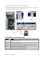
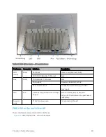
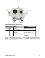
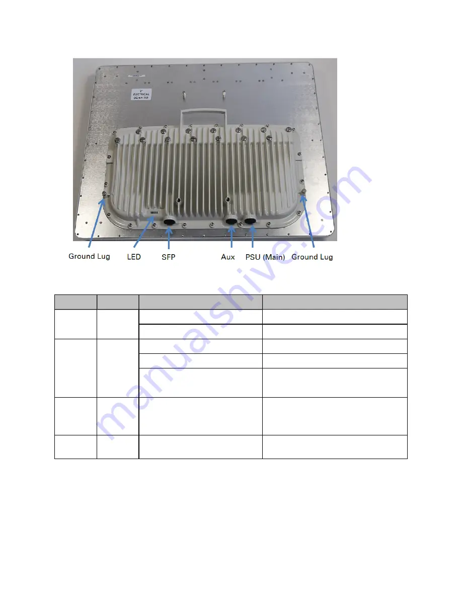
Table 57 :PMP 450m Series – AP rear interfaces
Port name
Connector
Interface
Description
PSU
(Main)
RJ45
PoE input
Power over Ethernet (PoE).
10/100/1000BASE-T Ethernet
Data
Aux
RJ45
10/100BASE-T Ethernet
Data
PoE output
Standard IEEE802.3at PoE.
Sync input/output
Connection and powering of UGPS
Sync input
SFP
SFP
2.5 Gbps Fiber Ethernet and 1 Gbps
Copper
Data and Management Services.
Plug-in SFP module must be purchased
separately.
Ground
Lugs
10 AWG copper wire
For grounding the unit
PMP 4 50 m Ser ies 3 GHz A P
These interfaces are described in ODU interfaces.
Figure 23 :
PMP 450m 3 GHz - AP rear interfaces
Summary of Contents for PMP 450 Series
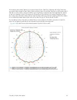
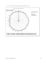
Page 92: ...Chapter 2 System hardware 92 Figure 29 MicroPoP Omni antenna implementation pattern Vertical...
Page 134: ...Chapter 3 System planning 134 Figure 51 Mast or tower installation...
Page 135: ...Chapter 3 System planning 135 Figure 52 Wall installation...
Page 136: ...Chapter 3 System planning 136 Figure 53 Roof installation...
Page 137: ...Chapter 3 System planning 137 Figure 54 GPS receiver wall installation...
Page 158: ...Chapter 3 System planning 158 Figure 61 cnMedusa Antenna...


