Chapter 2: System hardware
89
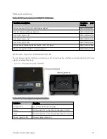
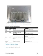
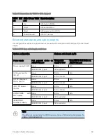
Port name
Connector
Interface
Description
Port
Pins 7 & 8 = +30 V DC
Pins 4 & 5 = Return
10/100/1000BASE-
T Ethernet
Data
Aux Port
Standard
TRRS 3.5 mm
headphones
Alignment audio
tone output
3.5 mm audio jack for alignment tone
GPS
synchronization
input or output
Timing signal input for Backhaul Master (BHM)
applications. Connects to cnPulse/UGPS Aux Port.
Can also be configured to provide sync out when in
BHM/BHS/SM modes
cnPulse/UGPS can also be powered from the 450b
Aux port
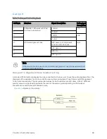
Note 1: GUI option "Sync Aux Port Configuration” controls the behavior of the Aux port.
Note 2: Pin-out detail for Aux port: -
Tip:
Alignment Tone (Default) / GPS Sync 1PPS IN (cnPulse) or GPS Sync 1PPS Out (Remote AP).
Ring 1:
c5 V Power Out / Alignment Tone Stereo Out.
Ring 2:
Sleeve:
cnPulse Serial Data In.
Ground
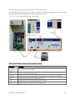
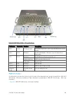
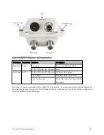
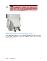
PMP 4 50 Micro Po P A P
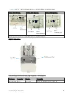
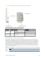
These interfaces are described in "PMP 450 MicroPoP Series – ODU rear interfaces" on the next page.
Summary of Contents for PMP 450 Series
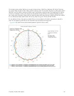
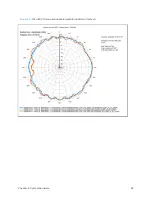
Page 92: ...Chapter 2 System hardware 92 Figure 29 MicroPoP Omni antenna implementation pattern Vertical...
Page 134: ...Chapter 3 System planning 134 Figure 51 Mast or tower installation...
Page 135: ...Chapter 3 System planning 135 Figure 52 Wall installation...
Page 136: ...Chapter 3 System planning 136 Figure 53 Roof installation...
Page 137: ...Chapter 3 System planning 137 Figure 54 GPS receiver wall installation...
Page 158: ...Chapter 3 System planning 158 Figure 61 cnMedusa Antenna...

