Chapter 2: System hardware
94
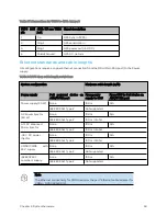
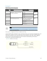
Table 63 :Connections for UGPS to 450b Aux port
UGPS RJ11
pin
450b 3.5 mm TRRS
jack
Signal description
1
Tip
GPS Sync in (1PPS)
3
Ring 2
GPS serial data in
4
Ring 1
GPS power out (+5 V DC)
6
Shield/Ground
GPS 0 V (return)
Et her net st and ar d s and cab le leng t hs
All configurations require a copper Ethernet connection from the ODU (Main PSU port) to the Power
supply.
Table 64 :PSU drop cable length restrictions
System configuration
Maximum cable length (m/ft)
Power supply
PoE powered
device on
AUX/SYNC port
From power
supply to ODU
From ODU to PoE device on
AUX/SYNC port
Power supply (30 W)
None
100 m
N/A
IEEE 802.3at Type 2
Not supported
AC Power Injector
(60 W)
None
100 m
N/A
IEEE 802.3at Type 2
100 m in total
AC+DC enhanced
Power Injector
None
100 m
N/A
IEEE 802.3at Type 2
100 m in total
-48 V DC power
injector
None
100 m
N/A
IEEE 802.3at Type 2
100 m in total
CMM4/CMM5
with
56 V supply
None
100 m
N/A
IEEE 802.3at Type 2
Not supported
IEEE802.3at
compliant supply
None
100 m
N/A
IEEE 802.3at Type 2
Not supported
Note
The Ethernet connectivity for CMM4 requires the part “Ethernet cable adapter for
CMM4 – N000045L001A”.
Summary of Contents for PMP 450 Series
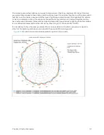
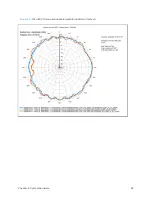
Page 92: ...Chapter 2 System hardware 92 Figure 29 MicroPoP Omni antenna implementation pattern Vertical...
Page 134: ...Chapter 3 System planning 134 Figure 51 Mast or tower installation...
Page 135: ...Chapter 3 System planning 135 Figure 52 Wall installation...
Page 136: ...Chapter 3 System planning 136 Figure 53 Roof installation...
Page 137: ...Chapter 3 System planning 137 Figure 54 GPS receiver wall installation...
Page 158: ...Chapter 3 System planning 158 Figure 61 cnMedusa Antenna...

