Chapter 4: Preparing for installation
198
Co nf ig uring Link f o r Test
It is important to stage the AP/BHM and SM/BHS units first to verify proper registration before deploying
the modules to the site. To begin configuring the modules for test, see the sections below:
Conf ig ur ing t he m anag em ent PC
To configure the local management PC to communicate with the AP, SM, BHM or BHS, proceed as follows:
Pow ering t he AP/ SM/ BH for t est configurat ion
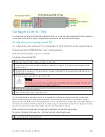
Perform the following steps to power on the ODU.
Procedure 2 Powering the ODU
1
Plug one end of a CAT 5 Ethernet cable into the ODU.
2
Plug the Ethernet cable connector labeled To Radio into the jack in the pig tail that hangs from the
power supply.
3
Plug the other connector of the pig tail (this connector labeled To Computer) into the Ethernet jack
of the computing device.
4
Plug the power supply into an electrical outlet.
Warning
From this point until you remove power from the ODU, stay at least as far from the AP
as the minimum separation distance specified.
5
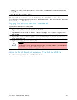
Power up the computing device
6
Start the browser in the computing device
The AP/BHM interface provides a series of web pages to configure and monitor the unit. Access web-
based interface through a computing device that is either directly connected or connected through a
network to the AP/BHM. If the computing device is not connected to a network when it is being configured
for test environment, and if the computer has used a proxy server address and port to configure a module,
then the operator may need to first disable the proxy setting in the computer.
Perform the following procedure to toggle the computer to not use the proxy setting.
Procedure 3 Bypassing browser proxy settings to access module web pages
1
Launch Microsoft Internet Explorer
Summary of Contents for PMP 450 Series
Page 92: ...Chapter 2 System hardware 92 Figure 29 MicroPoP Omni antenna implementation pattern Vertical...
Page 134: ...Chapter 3 System planning 134 Figure 51 Mast or tower installation...
Page 135: ...Chapter 3 System planning 135 Figure 52 Wall installation...
Page 136: ...Chapter 3 System planning 136 Figure 53 Roof installation...
Page 137: ...Chapter 3 System planning 137 Figure 54 GPS receiver wall installation...
Page 158: ...Chapter 3 System planning 158 Figure 61 cnMedusa Antenna...

