Chapter 5: Installation
230
l
ALWAYS wear cut-resistant gloves (check the label to ensure they are cut
resistant).
l
ALWAYS wear protective eyewear.
l
ALWAYS use a rotary blade tool to strip the cable (DO NOT use a bladed
knife).
Warning
Failure to obey the following precautions may result in injury or death:
l
Use the proper hoisting grip for the cable being installed. If the wrong
hoisting grip is used, slippage or insufficient gripping strength will result.
l
Do not reuse hoisting grips. Used grips may have lost elasticity, stretched,
or become weakened. Reusing a grip can cause the cable to slip, break, or
fall.
l
The minimum requirement is one hoisting grip for each 60 m (200 ft) of
cable.
Cut t o lengt h and fit hoist ing grips
1
Cut the main drop cable to length from the top LPU to the bottom LPU.
2
Slide one or more hoisting grips onto the top end of the drop cable.
3 Secure the hoisting grip to the cable using a special tool, as recommended by the manufacturer.
Terminat e w it h RJ4 5 connect ors
Caution
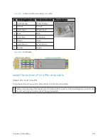
Check that the crimp tool matches the RJ45 connector, otherwise the cable or
connector may be damaged.
1
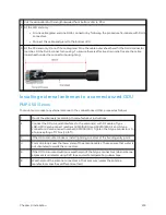
Strip the cable outer sheath and fit the RJ45 connector load bar.
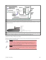
2
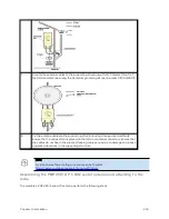
Fit the RJ45 connector housing as shown. To ensure there is effective strain relief, locate the cable
inner sheath under the connector housing tang.
Summary of Contents for PMP 450 Series
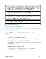
Page 92: ...Chapter 2 System hardware 92 Figure 29 MicroPoP Omni antenna implementation pattern Vertical...
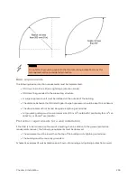
Page 134: ...Chapter 3 System planning 134 Figure 51 Mast or tower installation...
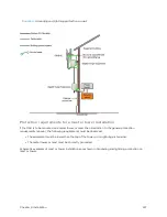
Page 135: ...Chapter 3 System planning 135 Figure 52 Wall installation...
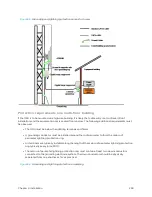
Page 136: ...Chapter 3 System planning 136 Figure 53 Roof installation...
Page 137: ...Chapter 3 System planning 137 Figure 54 GPS receiver wall installation...
Page 158: ...Chapter 3 System planning 158 Figure 61 cnMedusa Antenna...


