Chapter 1: Product description
32
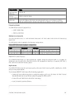
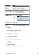
Table 10 :PMP 450 MicroPoP Series hardware configurations
ODU
Frequency
ODU type
PMP 450
MicroPoP
4.9 to 5.925 GHz
(support 4.9, 5.1, 5.2, 5.4 and 5.8
GHz)
Integrated Omni
9 dBi Integrated antenna
Integrated
Sector
13 dBi integrated
antenna
PMP/ PTP 4 50 b Ret ro Series
The PMP/PTP 450b Retro Series is a high- performance wireless bridge for Ethernet traffic. It is a
Subscriber Module based on the PMP 450b Series hardware, available with an integrated antenna and with
the same form factor of the PMP 450 SM, which allows reuse of the same reflector dish.
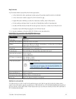
Key Features
The Cambium PMP/PTP 450b Retro Series offers the following benefits:
l
Ultra-wide band radios support the entire band from 4.9 to 5.925 GHz.
l
Gigabit Ethernet Interface provides the maximum transfer rates to the device.
l
3.5 mm audio jack allows direct connection of headphones without any adapters.
l
Updated FPGA enhances Packet Processing Power more than 4 times that of the 450m SM.
l
Capable of up to 300 Mbps aggregate in a 40 MHz channel.
l
Same form factor of the PMP 450 SM.
l
The form factor allows use of existing Offset Reflector dishes.
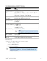
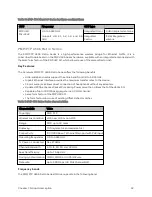
Table 11 :PMP 450 Retro Series characteristics
Characteristic
Value
Topology
PMP, PTP
Wireless link condition
LOS, near LOS or non-LOS
Range
PMP: up to 40 miles
Duplexing
TDD (symmetric and asymmetric)
Connectivity
100/1000Base-T Ethernet Main port with PoE input
Operating frequencies
4.9 to 5.925 GHz
Tx Power - conducted
Max 27 dBm
Channel bandwidth
5, 10, 15, 20, 30, and 40 MHz
Spectral efficiency
Up to 7.5 bps/Hz
Timing synchronization CMM4, CMM5, or UGPS/cnPulse
Data rate
Up to 300 Mbps (40 MHz channel BW).
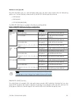
Frequency bands
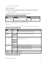
The PMP/PTP 450b Retro Series ODU can operate in the following band:
Summary of Contents for PMP 450 Series
Page 92: ...Chapter 2 System hardware 92 Figure 29 MicroPoP Omni antenna implementation pattern Vertical...
Page 134: ...Chapter 3 System planning 134 Figure 51 Mast or tower installation...
Page 135: ...Chapter 3 System planning 135 Figure 52 Wall installation...
Page 136: ...Chapter 3 System planning 136 Figure 53 Roof installation...
Page 137: ...Chapter 3 System planning 137 Figure 54 GPS receiver wall installation...
Page 158: ...Chapter 3 System planning 158 Figure 61 cnMedusa Antenna...


