Chapter 2: System hardware
74
Pow er sup p ly – PMP 4 50 m Ser ies
The PMP 450m Series - 5 GHz AP supports powering from the following power sources:
l
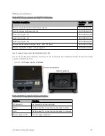
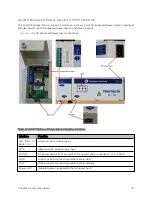
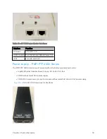
AC+DC Enhanced Power Injector (see AC+DC Enhanced Power Injector C000065L002C)
l
CMM5 56 V power and sync injector module with external 240 W or 600 W power supply
PSU part numbers
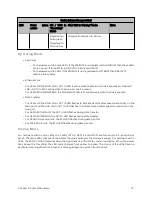
Table 44 :PSU part numbers for PMP 450m AP (5/3 GHz)
AP
Model
Cambium description
Cambium part number
5 GHz
AC+DC Enhanced Power
Injector
C000065L002C
3 GHz
Power Supply, AC, 54 V 240 W
N000000L054B
Pow er sup p ly – PMP/ PTP 4 50 i Ser ies
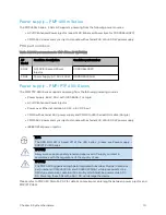
The PMP/PTP 450i Series supports powering from the following powering sources:
l
Power Supply, 60 W, 56 V with 1000BASE-T or GigE
l
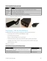
AC+DC Enhanced Power Injector
l
Power over Ethernet midspan, 60 W, -48 V DC Input
l
CMM4 with external 56 V power supply and CMM4 to 450i Series ODU cable (Dongle)
l
CMM5 56 V power and sync injector module with external 240 W or 600 W power supply
l
IEEE802.3at power injector
Note
The 900 MHz SM is based off of the 450 Series , please see Power supply –
PMP/PTP 450 Series .
Warning
Always use an appropriately rated and approved AC supply cord-set in
accordance with the regulations of the country of use.
Warning
The PMP 450 Ruggedized High Gain Integrated Subscriber Module (Cambium
part numbers C035045C014A and C036045C014A), while encapsulated in a
450i-type enclosure, contains 450 circuitry which must be powered via 30 V
DC. Powering these SMs with a 56 V DC will damage the device.
Please refer to PMP 450 MicroPoP AP for details on maximum cable lengths between power injector and
PMP/PTP 450i.
Summary of Contents for PMP 450 Series
Page 92: ...Chapter 2 System hardware 92 Figure 29 MicroPoP Omni antenna implementation pattern Vertical...
Page 134: ...Chapter 3 System planning 134 Figure 51 Mast or tower installation...
Page 135: ...Chapter 3 System planning 135 Figure 52 Wall installation...
Page 136: ...Chapter 3 System planning 136 Figure 53 Roof installation...
Page 137: ...Chapter 3 System planning 137 Figure 54 GPS receiver wall installation...
Page 158: ...Chapter 3 System planning 158 Figure 61 cnMedusa Antenna...

