Chapter 2: System hardware
System Components
Page 2-9
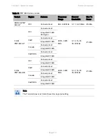
Table 16 PMP/PTP 450i Series - AP/SM/BH interface descriptions and cabling
Interface
Function
Cabling
PSU/Ethernet
Power-over-Ethernet, Ethernet
communications (management and data),
CMM sync-over-power synchronization
input
RJ45 Cable
See
Table 86
on page
5-11
Aux/Sync
GPS synchronization input and output,
UGPS power output
RJ 45 Cable
See
Table 87
on page
5-11
Audio tones
Data
RF Port A
Vertical RF connection to antenna
50 ohm RF cable, N-type
RF Port B
Horizontal RF connection to antenna
50 ohm RF cable, N-type
Ground Lugs
For grounding the unit
10 AWG copper wire
Note
If the Aux port will be used, a second Ethernet Gland will need to be ordered (Part
Number: N000065L033A).
PMP/PTP 450 Series interfaces - AP
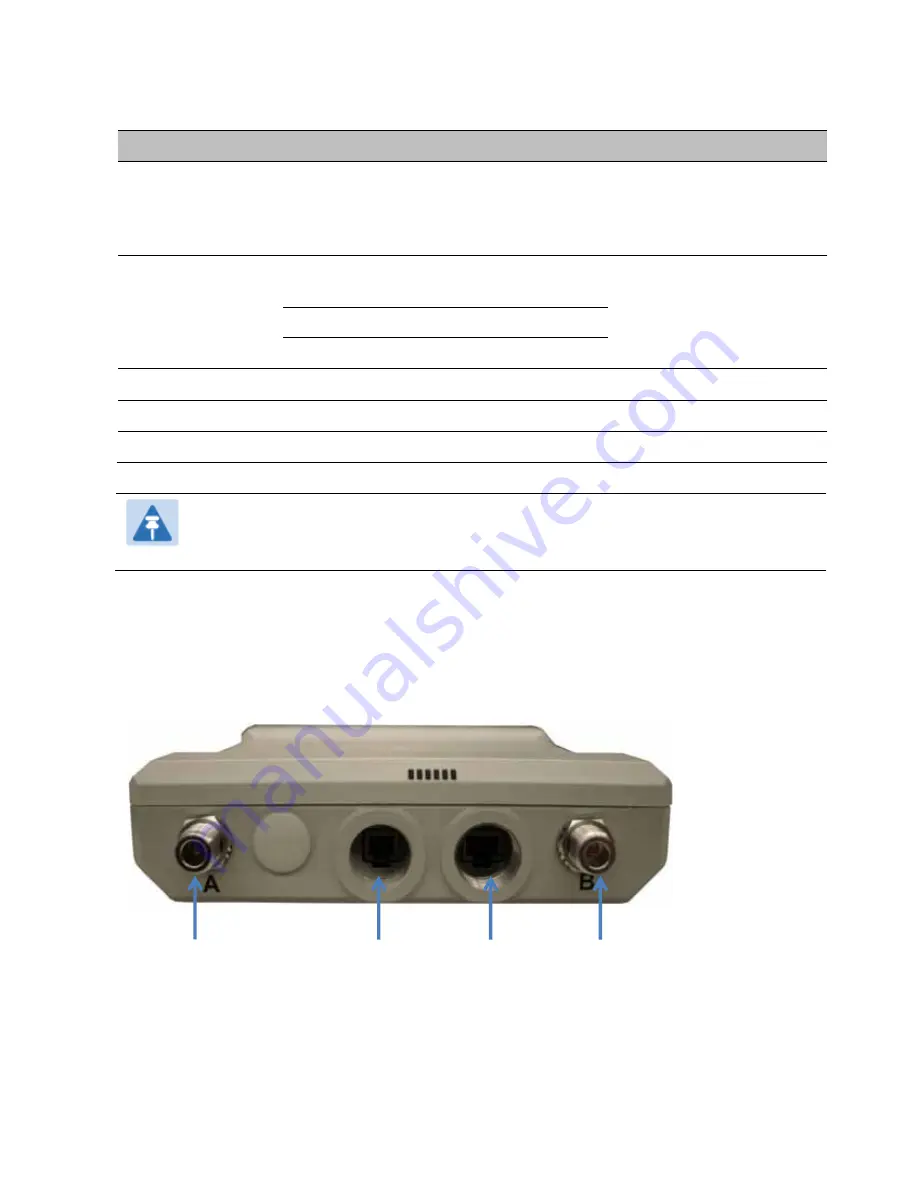
The PMP 450 Series - AP interfaces are illustrated below.
Figure 3 PMP/PTP 450 Series - AP interfaces
RF Port A
Sync/Default
Ethernet
RF port B


