background image


UNDER DEVELOPMENT 

Page 35 


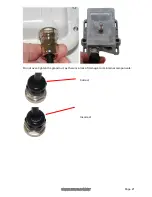
AC+DC power injector: 


Undo the retaining screw: 


Hinge back the cover: 


Plug the drop cable into the port: 


Close the cover and secure with the screw: 


Summary of Contents for PTP 650

Page 1: ...Cambium PTP 650 Installation Guide UNDER DEVELOPMENT ...

Page 2: ...copyrighted material Accordingly any copyrighted material of Cambium Networks its licensors or the 3rd Party software supplied material contained in the Cambium Networks products described in this document may not be copied reproduced reverse engineered distributed merged or modified in any manner without the express written permission of Cambium Networks Furthermore the purchase of Cambium Networ...

Page 3: ...se in outdoor radio equipment installation Related documents For full PTP 650 installation planning instructions refer to the PTP 650 Series User Guide Version information Document number and version phn 3350_000v002 Date of publication July 2013 Waste Electrical and Electronic Equipment WEEE For instructions on waste disposal of used products refer to http www cambiumnetworks com support ...

Page 4: ...e of grounding conductors and connection requirements for grounding electrodes Other regulations may apply in different countries and therefore it is recommended that installation of the outdoor unit be contracted to a professional installer PSU Always use one of the Cambium PTP 650 Series power supply units PSU to power the ODU Failure to use a Cambium supplied PSU could result in equipment damag...

Page 5: ...allowed in some countries for safe handling in wet conditions and therefore may create a safety hazard RF exposure near the antenna Strong radio frequency RF fields will be present close to the antenna when the transmitter is on Always turn off the power to the ODU before undertaking maintenance activities in front of the antenna Minimum separation distances Ensure that personnel are not exposed t...

Page 6: ...ues must be used for the connection of dissimilar metals Siting ODUs and antennas ODUs and external antennas are not designed to survive direct lightning strike For this reason they must be installed in Zone B as defined in PTP 650 Series User Guide Mounting in Zone A may put equipment structures and life at risk Optical SFP module The optical SFP module is a Class 1 Laser product When installing ...

Page 7: ...er Injector Extended Temperature and Capacity C000065L002 US Line Cord Fig 8 N000065L003 UK Line Cord Fig 8 N000065L004 EU Line Cord Fig 8 N000065L005 Australia Line Cord Fig 8 N000065L006 The AC DC Power Injector is required if the ODU has an AUX interface Connectorized ODU accessories For connectorized ODUs Cambium Networks supply RF cable and connectors as follows Cambium description Cambium pa...

Page 8: ...n Cambium part number 1000 ft Reel Outdoor Copper Clad CAT5E WB3175 328 ft 100 m Reel Outdoor Copper Clad CAT5E WB3176 Cable Grounding Kits For 1 4 And 3 8 Cable 01010419001 Tyco AMP Mod Plug RJ45 100 pack WB3177 Tyco AMP Crimp Tool WB3211 RJ 45 Gland Spare PG16 style Qty 10 N000065L033 PTP 650 LPU and Grounding Kit C000065L007 SFP modules Cambium Networks supplie SFP modules as follows Cambium de...

Page 9: ...er or building for the outdoor equipment ODU and optional external antenna and an equipment building or moisture proof enclosure for the indoor equipment PSU In the basic configuration there is only one Ethernet interface a copper Cat5e connection from the ODU PSU port to the PSU and network terminating equipment as shown here ...

Page 10: ...ced configurations there may be an optical or copper Cat5e SFP Ethernet interface unpowered into the ODU SFP port In more advanced configurations there may be a copper Cat5e interface with optional power over Ethernet into the ODU AUX port ...

Page 11: ... EMC cable glands supplied in the ODU kits with silver caps as these may only be used in PTP 650 installations without LPUs ODU and top LPU mounting options Select one of two mounting options for the ODU and top LPU The AUX interface requires its own LPUs The copper SFP interface requires its own surge arrestors not PTP 650 LPUs The optical SFP interface does not require LPUs or ground cables ...

Page 12: ...y lead to failure of the assembly Note ODUs are shipped with blanking plugs protecting the PSU AUX and SFP ports Use a large flat blade screwdriver to remove the plugs from those ports that will be connected to interface cables 1 Confirm that the correct mounting bracket kit has been supplied Integrated ODU Connectorized ODU ...

Page 13: ...ounting plate and bracket bolts to the back of the ODU using the bolts and washers provided Use the bracket bolt receptacles as shown 4 Hoist the ODU up to its mounting position 5 LPU mounting option 1 back to back only Discard the ODU bracket strap it is replaced by the LPU Fix the ODU and LPU to the mounting pole using the bolts flat washers and coil washers provided in the bracket kit Mount the...

Page 14: ...d ODU Connectorized ODU 7 LPU mounting option 2 separate only Use the U bolt bracket from the LPU kit to mount the LPU on the pole below the ODU Mount the LPU vertically with cable entry holes facing downwards 8 Integrated ODU only Adjust the elevation E and azimuth A of the unit to achieve visual alignment 9 Tighten all three ODU bracket bolts to the required torque setting of 14 Nm 11 lb ft ...

Page 15: ... the ODU ensure that all top LPUs are grounded at the same ODU grounding point 1 Fasten one ground cable to each ODU grounding point using the M6 small lugs one is for the top LPU M6 lug at other end and the other is for the tower or building M10 lug at other end It does not matter which cable goes on which grounding point Tighten both grounding bolts to a torque of 5 Nm 3 9 lb ft M6 lug M6 lug M6...

Page 16: ...ten both nuts to a torque of 5 Nm 3 9 lb ft Locking nut Washer M6 lug Washer Nut Toothed washer M6 lug to ODU 3 Select a tower or building grounding point within 0 3 meters 1 ft of the ODU bracket on the same metal Remove paint from the surface and apply anti oxidant compound Fasten the ODU grounding cable to this point using the M10 large lug ...

Page 17: ...ways use crimped N type connectors at the ODU and antenna Caution Ensure that no undue strain is placed on the ODU or antenna connectors Ensure that the cables do not flap in the wind as flapping cables are prone to damage and induce unwanted vibrations in the supporting structure Note When using separate antennas to achieve spatial diversity the antenna cables will be disconnected from the ODU du...

Page 18: ...rization antenna Tighten the N type connectors using a torque wrench set to 15 lb in or 1 7 Nm 3 If the ODU is to be mounted indoors install lightning arrestors at the building entry point Connect the lighting arrestors to the master ground bar of the building 4 When dressing the antenna cables form drip loops near the lower ends These ensure that water is not constantly channeled towards the conn...

Page 19: ...different method 7 Ground the antenna cables to the supporting structure at the correct points They should be grounded within 0 3 meters 1 foot of the ODU and antennas using the Cambium grounding kit part number 01010419001 8 Dress the antenna cables and attach them to the supporting structure using site approved methods ...

Page 20: ...es into the SFP or AUX ports of the ODU but with the following differences In SFP copper Cat5e interfaces install a copper SFP module in the ODU SFP port Connect the SFP drop cable into this module using the long cable gland from the SFP module kit The PTP 650 Ethernet SFP Module Installation Guide supplied with Cambium Networks SFP modules describes how to do this PTP 650 LPUs are not suitable fo...

Page 21: ...rounding kit to both ends of the 600 mm length of pre terminated cable supplied in the LPU and grounding kit 1 Disassemble the gland 2 Thread each part onto the cable the rubber bung is split 3 Assemble the spring clip and the rubber bung 4 Fit the parts into the body and lightly screw on the gland nut do not tighten it ...

Page 22: ...f cable gland and RJ45 connector to the ODU and LPU 1 Plug the RJ45 connector into the socket in the unit ensuring that it snaps home 2 Fit the gland body to the ODU or LPU port and tighten it to a torque of 5 5 Nm 4 3 lb ft 3 Fit the gland nut and tighten until the rubber seal closes on the cable ...

Page 23: ...UNDER DEVELOPMENT Page 21 Do not over tighten the gland nut as there is a risk of damage to its internal components Correct Incorrect ...

Page 24: ...lief cable gland and RJ45 connector from the ODU as illustrated or LPU 1 Remove the gland nut Wiggle the drop cable to release the tension of the gland body When the tension in the glad body is released a gap opens at the point shown 2 Unscrew the gland body Use a small screwdriver to press the RJ45 locking tab then remove the connector ...

Page 25: ...s Used grips may have lost elasticity stretched or become weakened Reusing a grip can cause the cable to slip break or fall The minimum requirement is one hoisting grip for each 60 m 200 ft of cable 1 Cut drop cable to length required from top LPU to bottom LPU 2 Slide one or more hoisting grips onto the top end of the drop cable 3 Secure the hoisting grip to the cable using a special tool as reco...

Page 26: ...de tool to strip the cable DO NOT use a bladed knife Caution Check that the crimp tool matches the RJ45 connector otherwise the cable or connector may be damaged 1 Thread the cable gland onto the drop cable Do not tighten the gland nut 2 Strip the cable end and fit the RJ45 connector load bar To use the rotary blade tool fit it around the outer cable sheath and rotate the cutter around the cable o...

Page 27: ...e clamp is securely in place Maintain tension on the hoisting grip during hoisting Loss of tension can cause dangerous movement of the cable and result in injury or death to personnel Do not release tension on the grip until after the grip handle has been fastened to the supporting structure 1 Hoist the top end of the main drop cable up to the top LPU following the hoist manufacturer s instruction...

Page 28: ...P 650 Series User Guide Caution Install ground cables without drip loops and pointing down towards the ground otherwise they may not be effective 1 Remove 60 mm 2 5 inches of the drop cable outer sheath 2 Cut 38mm 1 5 inches of rubber tape self amalgamating and fit to the ground cable lug Wrap the tape completely around the lug and cable 3 Fold the ground wire strap around the drop cable screen an...

Page 29: ... the cable ties 5 Cut a 38mm 1 5 inches section of self amalgamating tape and wrap it completely around the joint between the drop and ground cables 6 Use the remainder of the self amalgamating tape to wrap the complete assembly Press the tape edges together so that there are no gaps ...

Page 30: ... to top The edges of each layer should be 25mm 1 inch above A and 25 mm 1 inch below B the previous layer 9 Prepare the metal grounding point of the supporting structure to provide a good electrical contact with the grounding cable clamp Remove paint grease or dirt if present Apply anti oxidant compound liberally between the two metals 10 Clamp the bottom lug of the grounding cable to the supporti...

Page 31: ...sic configuration there is one bottom LPU for the PSU drop cable In a more advanced configuration there may be two bottom LPUs one for the PSU and one for a copper SFP drop cable Mount both LPUs within 600 mm 24 in of the building entry point 2 Connect the main drop cable to the bottom LPU by following the procedure Connecting a drop cable to the ODU and LPU on page 20 3 Fasten one ground cable to...

Page 32: ...inate the bottom LPU to PSU drop cable with RJ45 connectors at both ends and with a cable gland at the LPU end Warning The metal screen of the drop cable is very sharp and may cause personal injury ALWAYS wear cut resistant gloves check the label to ensure they are cut resistant ALWAYS wear protective eyewear ALWAYS use a rotary blade tool to strip the cable DO NOT use a bladed knife Caution Check...

Page 33: ...cting a drop cable to the ODU and LPU on page 20 4 At the PSU end only Do not fit a cable gland Strip the cable end and fit the RJ45 connector load bar To use the rotary blade tool fit it around the outer cable sheath and rotate the cutter around the cable once or twice then remove the stripped outer section 5 At the PSU end only Fit the RJ45 connector housing as shown To ensure there is effective...

Page 34: ...ests Pins 1 and 2 Ohms 20 Ohms 60 Ohms 2 Pass Fail These resistances must be within 10 of each other 1 Circle Pass or Fail Pass Fail Pins 3 and 6 Ohms 20 Ohms 60 Ohms 2 Pass Fail Pins 4 and 5 Ohms 20 Ohms 60 Ohms 2 Pass Fail Pins 7 and 8 Ohms 20 Ohms 60 Ohms 2 Pass Fail Pin 1 and screen ODU ground K Ohms 100K Ohms 3 Pass Fail Pin 8 and screen ODU ground K Ohms 100K Ohms 3 Pass Fail 1 Ensure that t...

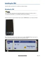
Page 35: ...proof locate them away from sources of moisture either in the equipment building or in a ventilated moisture proof enclosure Place the AC power injector Cambium part number N000065L001 on a horizontal surface Mount the AC DC power injector Cambium part number C000065L002 by screwing it to a vertical or horizontal surface using the four screw holes circled ...

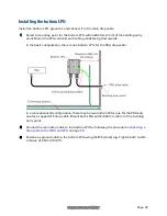
Page 36: ...other equipment may damage the ODU and or the other equipment Caution Do not dress the PSU cables too tightly as this may make the connections unreliable Caution The connected network equipment must feature screened RJ45 connectors and must be connected to ground otherwise the PSU will not be grounded 1 Form a drip loop on the PSU end of the LPU PSU drop cable The drip loop ensures that any moistu...

Page 37: ...UNDER DEVELOPMENT Page 35 3 AC DC power injector Undo the retaining screw Hinge back the cover Plug the drop cable into the port Close the cover and secure with the screw ...

Page 38: ... ground otherwise the PSU will not be grounded Note The PSU is not normally connected to the network equipment until antenna alignment is complete 1 Prepare the Cat5e cable that will connect the PSU to the network equipment 2 When the system is ready for network connection connect the Cat5e cable to the LAN port of the PSU AC power injector AC DC power injector ...

Page 39: ... in the most challenging non line of sight RF environments Our flexible Point to Multipoint PMP solutions operate in the licensed unlicensed and federal frequency bands providing reliable secure cost effective access networks With more than three million modules deployed in networks around the world our PMP access network solutions prove themselves day in and day out in residential access leased l...

Reviews: