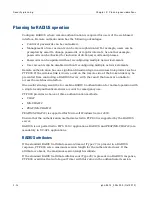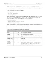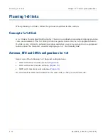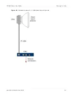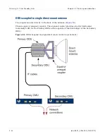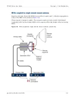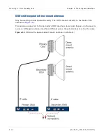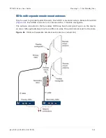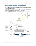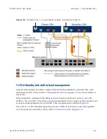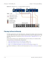
Planning 1+ 1 Hot St andby links
Chapt er 2: Planning considerat ions
2- 42
phn- 2513_004v000 ( Oct 2012)
Designating primary and secondary units
At each link end, designate one unit as Primary and the other as Secondary, applying the
following criteria:
•
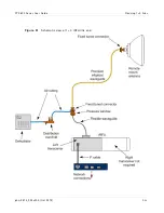
The Primary CMU is connected to the ODU or IRFU transceiver with the best link
budget. In ODU deployments with unequal couplers, this is the ODU connected to the
arm of the coupler with the lowest path loss. The coupler labels this arm as "Main".
•
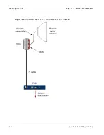
If separate antennas are deployed, the Primary CMU is connected to the ODU that is
connected to the antenna with the highest gain. If equal gain antennas are used, either
CMU can be configured as the Primary.
•
In IRFU deployments, the Primary CMU is connected to the left hand transceiver.
The procedure for configuring the primary and secondary units is described in
).
Link Planning for 1+1 Hot Standby links
A 1+1 Hot Standby link has four radio paths:
•
Primary end A to Primary end B
•
Primary end A to Secondary end B
•
Secondary end A to Primary end B
•
Secondary end A to Secondary end B
A 1+1 Hot Standby link normally operates on the Primary to Primary radio path. However,
any of the four paths may become active if a fault causes a protection switch at one end of
the link. Use LINKPlanner to check wireless link availability for all four paths, ensuring
that the minimum required availability can be met by all paths.
Summary of Contents for PTP 800 Series
Page 1: ...Cambium PTP 800 Series User Guide System Release 800 05 02 ...
Page 40: ...Licensing requirements About This User Guide 10 phn 2513_004v000 Oct 2012 ...
Page 232: ...Limit of liability Chapter 3 Legal information 3 22 phn 2513_004v000 Oct 2012 ...
Page 322: ...Radiation hazard assessm ent Chapter 4 Reference information 4 90 phn 2513_004v000 Oct 2012 ...
Page 428: ...Replacing IRFU components Chapter 5 Installation 5 106 phn 2513_004v000 Oct 2012 ...
Page 630: ...Using recovery mode Chapter 7 Operation 7 78 phn 2513_004v000 Oct 2012 ...

