PTP 800 Series User Guide
Managing perform ance
phn- 2513_004v000 ( Oct 2012)
7- 59
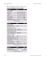
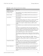
Ta ble 2 6 1
Syst em St at ist ics and Count er s at t r ibut es
At t r ibu t e
M e a n in g
System Statistics
Transmit Power
The maximum, mean, minimum and latest measurements of
Transmit Power.
Receive Power
The maximum, mean, minimum and latest measurements of
Receive Power.
Vector Error
The maximum, mean, minimum and latest measurements of
Vector Error.
Normalized Mean Square Vector Error is a measure of quality
for the received signal after all corrections made by the
demodulator. The value is generally in the range from -3 dB to -
35 dB. A more negative number indicates a higher quality
signal.
Link Loss
The maximum, mean, minimum and latest measurements of Link
Loss.
Link Loss is a measurement of the loss in signal level as the
radio wave propagates between the antennas installed at each
end of the link. It is determined by measurement of the receive
level, the transmit power of the remote end and the antenna
gains and feeder losses at each end of the link.
The Link Loss is therefore only accurate if the correct antenna
gains and feeder losses have been configured at both ends of the
link.
Link Loss (dB) = Remote Transmit Power (dBm) - Remote
Feeder Loss (dB) + Remote Antenna Gain (dBi) + Local Antenna
Gain (dBi) - Local Feeder Loss (dB) - Local Receive Power
(dBm).
Transmit Data Rate
The data rate in the transmit direction, expressed in Mbps and
presented as: max, mean, min, and latest in an histogram
format. The max, min and latest are true instantaneous
measurements; the mean is the mean of a set of one second
means.
Receive Data Rate
The data rate in the receive direction, expressed in Mbps and
presented as: max, mean, min, and latest in an histogram
format. The max, min and latest are true instantaneous
measurements; the mean is the mean of a set of one second
means.
Summary of Contents for PTP 800 Series
Page 1: ...Cambium PTP 800 Series User Guide System Release 800 05 02 ...
Page 40: ...Licensing requirements About This User Guide 10 phn 2513_004v000 Oct 2012 ...
Page 232: ...Limit of liability Chapter 3 Legal information 3 22 phn 2513_004v000 Oct 2012 ...
Page 322: ...Radiation hazard assessm ent Chapter 4 Reference information 4 90 phn 2513_004v000 Oct 2012 ...
Page 428: ...Replacing IRFU components Chapter 5 Installation 5 106 phn 2513_004v000 Oct 2012 ...
Page 630: ...Using recovery mode Chapter 7 Operation 7 78 phn 2513_004v000 Oct 2012 ...

