background image

PTP 800 Series User Guide 

Ordering com ponent s 


phn- 2513_004v000 ( Oct  2012)  


2- 71


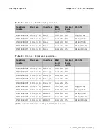
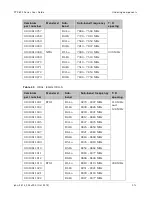
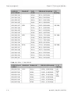
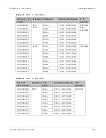
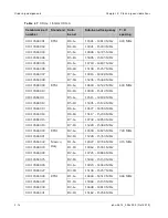
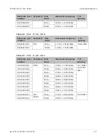
Ta ble  4 2   

ODUs:  7 GHz ODU- A 

Ca m b iu m  
pa r t  n u m be r  

St a n d a r d  

Su b-
ba n d  

Su b- b a n d  f r e q u e n cy   T/ R 

spa cin g  

01010610001 

ETSI 

B1-Lo 

7428 – 7484 MHz 

154 MHz 

01010610002 

B1-Hi 

7582 – 7638 MHz 

01010610003 

B2-Lo 

7470 – 7526 MHz 

01010610004 

B2-Hi 

7624 – 7680 MHz 

01010610005 

B3-Lo 

7512 – 7568 MHz 

01010610006 

B3-Hi 

7666 – 7722 MHz 

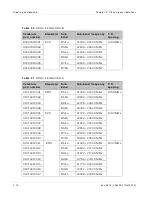
01010610013 

ETSI 

B1-Lo 

7114 – 7177 MHz 

161 MHz 

01010610014 

B1-Hi 

7275 – 7338 MHz 

01010610015 

B2-Lo 

7149 – 7212 MHz 

01010610016 

B2-Hi 

7310 – 7373 MHz 

01010610017 

B3-Lo 

7184 – 7247 MHz 

01010610018 

B3-Hi 

7345 – 7408 MHz 

01010610019 

B4-Lo 

7219 – 7282 MHz 

01010610020 

B4-Hi 

7380 – 7443 MHz 

01010610021 

B5-Lo 

7239 – 7302 MHz 

01010610022 

B5-Hi 

7400 – 7463 MHz 

01010610023 

B6-Lo 

7274 – 7337 MHz 

01010610024 

B6-Hi 

7435 – 7498 MHz 

01010610025 

B7-Lo 

7309 – 7372 MHz 

01010610026 

B7-Hi 

7470 – 7533 MHz 

01010610027 

B8-Lo 

7344 – 7407 MHz 

01010610028 

B8-Hi 

7505 – 7568 MHz 

01010610029 

B9-Lo 

7414 – 7477 MHz 

01010610030 

B9-Hi 

7575 – 7638 MHz 

01010610031 

B10-Lo 

7449 – 7512 MHz 

01010610032 

B10-Hi 

7610 – 7673 MHz 

01010610033 

B21-Lo 

7484 – 7547 MHz 

Summary of Contents for PTP 800 Series

Page 1: ...Cambium PTP 800 Series User Guide System Release 800 05 02 ...

Page 2: ...any copyrighted material of Cambium its licensors or the 3rd Party software supplied material contained in the Cambium products described in this document may not be copied reproduced reverse engineered distributed merged or modified in any manner without the express written permission of Cambium Furthermore the purchase of Cambium products shall not be deemed to grant either directly or by implic...

Page 3: ...roperly grounded It is the user s responsibility to install the equipment in accordance with national regulations In the USA follow Section 810 of the National Electric Code ANSI NFPA No 70 1984 USA In Canada follow Section 54 of the Canadian Electrical Code These codes describe correct installation procedures for grounding the ODU CMU mast lead in wire and discharge unit size of grounding conduct...

Page 4: ...s will be present close to the antenna when the transmitter is on Always mute the transmitter before undertaking maintenance activities in front of the antenna Ensure that people cannot stand or walk in front of the antenna within 10 degrees of the antenna axis and within the minimum distances listed in Table 210 ETSI or Table 211 FCC The minimum distances in these tables have been calculated usin...

Page 5: ...quirements 9 Operating license 9 Cambium license agreement 9 Chapter 1 Product description 1 1 Overview 1 2 Key features 1 2 Supported bands and frequencies 1 3 Typical users and applications 1 4 System components 1 5 Link types 1 6 Compact modem unit CMU 1 8 CMU description 1 8 CMU interfaces 1 9 Further reading on the CMU 1 12 Outdoor unit ODU 1 13 ODU description 1 13 ODU interfaces 1 14 Furthe...

Page 6: ...nections 1 34 Cable grounding ODU platforms only 1 34 Further reading on cabling and lightning protection 1 36 Wireless operation 1 37 Channel separation 1 37 Channel bandwidth 1 37 Modulation modes 1 38 Adaptive coding and modulation 1 38 Automatic transmitter power control 1 38 Maximum receive power 1 39 Maximum transmit power 1 40 Security 1 40 Further reading on wireless operation 1 40 Etherne...

Page 7: ...ve Diversity 1 67 Further reading on 1 1 Hot Standby 1 69 FIPS 140 2 1 70 FIPS 140 2 capability 1 70 FIPS 140 2 mode 1 71 Further reading on FIPS 140 2 1 72 Chapter 2 Planning considerations 2 1 Link planning 2 2 Process 2 2 Site selection 2 3 Wind loading 2 3 Maximum IF cable length 2 3 Power supply considerations 2 4 PTP LINKPlanner 2 5 Grounding and lightning protection 2 7 The need for power s...

Page 8: ... and CMU configurations for 1 0 2 30 Network configurations for 1 0 2 34 Planning 1 1 Hot Standby links 2 35 Concept of a 1 1 Hot Standby link 2 35 Antenna RFU and CMU configurations for 1 1 2 35 Designating primary and secondary units 2 42 Link Planning for 1 1 Hot Standby links 2 42 Network configurations for 1 1 2 43 Planning for Receive Diversity 2 46 Planning 2 0 links 2 49 Concept of a 2 0 l...

Page 9: ... 3 4 Confidentiality 3 4 Right to use Cambium s name 3 5 Transfer 3 5 Updates 3 5 Maintenance 3 5 Disclaimer 3 6 Limitation of liability 3 6 U S government 3 7 Term of license 3 7 Governing law 3 7 Assignment 3 8 Survival of provisions 3 8 Entire agreement 3 8 Third party software 3 8 Hardware warranty 3 20 Limit of liability 3 21 Chapter 4 Reference inform ation 4 1 Equipment specifications 4 2 C...

Page 10: ...ications 4 84 Radiation hazard assessment 4 86 ETSI method 4 86 FCC method 4 88 Chapter 5 I nstallation 5 1 Preparing for installation 5 2 Safety precautions during installation 5 2 Grounding and lightning protection requirements 5 2 Selecting installation options 5 2 Preparing personnel 5 3 Preparing inventory 5 3 Preparing tools 5 3 Unit pre configuration 5 4 Installing antennas and ODUs 5 5 Ins...

Page 11: ...e flexible waveguide to the IRFU 5 72 Connecting the CMU cables to the IRFU 5 73 Grounding the IRFU 5 74 Connecting power to the IRFU 5 76 Installing the CMU 5 77 Maximum operating ambient temperature for the CMU 5 77 Operation of CMU in a Restricted Access Location 5 77 Mounting the CMU 5 78 Grounding the CMU 5 80 Connecting the CMU to the IF cable 5 81 Connecting the CMU power supply 5 82 Prepar...

Page 12: ...ging into the web interface 6 6 Task 2 Configuring IP and Ethernet interfaces 6 8 Managing the units during configuration and alignment 6 8 Configuring the IP interface and management mode 6 10 Reconnecting to the management PC 6 19 Task 3 Installing license keys 6 21 Checking licensed capabilities 6 21 Generating a new license key 6 23 Entering a new license key 6 23 Starting the full capacity tr...

Page 13: ...agent 6 77 Configuring SNMPv3 agent 6 77 Configuring SNMPv1 2c agent 6 86 Task 9 Configuring alarms and messages 6 90 Configuring generation of diagnostics alarms 6 90 Configuring generation of email messages 6 92 Task 10 Configuring syslog 6 94 Configuring system logging syslog 6 94 Task 11 Configuring remote access 6 96 Configuring web based management attributes 6 96 Task 12 Aligning antennas 6...

Page 14: ...mary 7 6 Viewing the system status 7 7 Identifying a unit from the web browser title 7 12 Logging out 7 14 Managing alarms and events 7 15 Managing alarms 7 15 Managing email alerts 7 24 Managing SNMP traps 7 24 Managing event notification messages 7 31 Disabling and enabling the wireless interface 7 32 Disabling wireless transmission 7 32 Enabling wireless transmission 7 32 Managing 1 1 Hot Stand...

Page 15: ...ecking the recovery version 7 70 Using recovery mode 7 71 Entering recovery mode 7 71 Selecting recovery option 7 72 Upgrading software image 7 74 Resetting IP and Ethernet configuration to factory defaults 7 75 Erasing configuration 7 76 Zeroizing security parameters 7 76 Downgrading PTP 800 software 7 77 Chapter 8 Troubleshooting 8 1 Connecting to the web management interface 8 2 Check the CMU p...

Page 16: ...ennas 8 11 Check link status 8 11 Check IRFU status LEDs 8 12 Testing protection switchover 8 13 Check protection interface status 8 13 Check that protection switching is enabled 8 13 Check the status of the wireless interface 8 14 Check the link protection cable 8 14 Force a protection switchover 8 14 Check the configuration of the active and inactive units 8 14 Glossary I ...

Page 17: ...tion 1 24 Figure 16 IRFU transceiver interfaces 1 25 Figure 17 Typical PTP 800 antenna with ODU Cambium direct mount interface 1 27 Figure 18 Direct mount mechanical interface 1 28 Figure 19 ODU clipped onto direct mount mechanical interface 1 28 Figure 20 Remote mount antenna waveguide interface 1 28 Figure 21 RMK showing the ODU interface 1 30 Figure 22 RMK showing the waveguide interface 1 30 F...

Page 18: ...c view of 1 0 ODU direct mount link end 2 31 Figure 50 Schematic view of 1 0 ODU remote mount link end 2 32 Figure 51 Schematic view of 1 0 IRFU link end 2 33 Figure 52 Schematic view of network connections for a 1 0 link end 2 34 Figure 53 ODUs coupled to single direct mount antenna schematic 2 36 Figure 54 ODUs coupled to single remote mount antenna schematic 2 37 Figure 55 ODUs with separate di...

Page 19: ...igure 84 Cable loss plot for a 100 meter cable with no ODU 5 65 Figure 85 Cable loss plot for a 100 meter cable with ODU connected 5 65 Figure 86 DTF plot for a 17 meter cable with no ODU 5 68 Figure 87 DTF plot for a 17 meter cable with ODU connected 5 69 Figure 88 IRFU rack mounting 5 71 Figure 89 Partial rear view of IRFU with waveguide port 5 72 Figure 90 Connecting the coaxial cable to the IR...

Page 20: ... Security Configuration Wizard page 6 34 Figure 123 Step 1 Enter Key of Keys page 6 35 Figure 124 Step 2 TLS Private Key and Public Certificate page 6 36 Figure 125 Step 3 User Security Banner page 6 36 Figure 126 Step 4 Login Information Settings page 6 37 Figure 127 Step 5 Random Number Entropy Input page 6 37 Figure 128 Step 6 Enter Wireless Link Encryption Key page 6 38 Figure 129 Step 7 HTTP ...

Page 21: ...on page for SNMPv3 6 82 Figure 157 Step 5 SNMP Trap Configuration page for SNMPv3 6 83 Figure 158 Confirm SNMP Configuration page for SNMPv3 6 85 Figure 159 Step 1 SNMP Configuration page for SNMPv1 2c 6 86 Figure 160 Step 3 SNMP Trap Configuration page for SNMPv1 2c 6 87 Figure 161 Confirm SNMP Configuration page for SNMPv1 2c 6 89 Figure 162 Diagnostic Alarms page with protection alarms 6 91 Fig...

Page 22: ...nsmitter is muted 7 32 Figure 190 Protected Link page 7 33 Figure 191 Login Information page 7 52 Figure 192 Encryption key mismatch 7 55 Figure 193 Web Page Properties page 7 56 Figure 194 System Statistics and Counters page 7 58 Figure 195 Diagnostics page 1 0 or 2 0 link 7 62 Figure 196 Diagnostics page 1 1 link 7 63 Figure 197 Diagnostics Plotter page 7 64 Figure 198 Generate Downloadable Diag...

Page 23: ...e 14 Minimum transmit receive frequency separation at a 2 0 IRFU link end 2 56 Table 15 Optional components for PTP 800 CMUs 2 57 Table 16 Selecting antennas for each hardware configuration 2 59 Table 17 Antennas 6 GHz single polarization 2 60 Table 18 Antennas 6 GHz dual polarization 2 60 Table 19 Antennas 7 GHz and 8 GHz single polarization 2 61 Table 20 Antennas 7 GHz and 8 GHz dual polarizatio...

Page 24: ...le 48 ODUs 18 GHz ODU B 2 77 Table 49 ODUs 18 GHz ODU A 2 77 Table 50 ODUs 23 GHz ODU B 2 78 Table 51 ODUs 23 GHz ODU A 2 78 Table 52 ODUs 26 GHz ODU A 2 79 Table 53 ODUs 28 GHz ODU A 2 79 Table 54 ODUs 32 GHz ODU A 2 79 Table 55 ODUs 38 GHz ODU A 2 80 Table 56 Cable and LPU components 2 81 Table 57 Inventory of the coaxial cable installation assembly kit WB3616 2 83 Table 58 RMKs waveguides and a...

Page 25: ...ble 85 IRFU environmental specifications 4 9 Table 86 IRFU EMC and safety compliance 4 9 Table 87 IRFU transceiver power consumption 4 10 Table 88 Antenna transition waveguide and RMK flanges 4 11 Table 89 Torque value in Nm lb ft for each fastener size 4 15 Table 90 ODU coupler physical specifications 4 15 Table 91 ODU coupler environmental specifications 4 15 Table 92 ODU coupler return losses a...

Page 26: ...ration 4 34 Table 123 8 GHz ETSI with 28 MHz channel separation 4 34 Table 124 8 GHz ETSI with 29 65 MHz channel separation 4 34 Table 125 11 GHz FCC and Canada with 10 MHz bandwidth ODU A 4 35 Table 126 11 GHz FCC and Canada with 10 MHz bandwidth ODU B 4 35 Table 127 11 GHz FCC and Canada with 30 MHz bandwidth ODU A 4 36 Table 128 11 GHz FCC and Canada with 30 MHz bandwidth ODU B 4 36 Table 129 1...

Page 27: ... Table 159 18 GHz Brazil with 13 75 MHz channel separation 4 53 Table 160 18 GHz Brazil with 27 5 MHz channel separation 4 53 Table 161 18 GHz Brazil with 55 MHz channel separation 4 53 Table 162 23 GHz FCC and Canada with 10 MHz bandwidth ODU A 4 54 Table 163 23 GHz FCC and Canada with 10 MHz bandwidth ODU B 4 55 Table 164 23 GHz FCC and Canada with 20 MHz bandwidth ODU A 4 55 Table 165 23 GHz FC...

Page 28: ...Hz ETSI with 28 MHz channel separation 4 70 Table 196 38 GHz ETSI with 56 MHz channel separation 4 70 Table 197 Copper data port specifications 4 71 Table 198 Fiber data port specifications 4 71 Table 199 Management port specifications 4 71 Table 200 Ethernet bridging specifications 4 72 Table 201 Event messages 4 74 Table 202 Standard SNMP objects 4 77 Table 203 Identification of interfaces 4 79 ...

Page 29: ...nse Configuration attributes 6 71 Table 234 Step 3 Wireless Configuration attributes 6 72 Table 235 Step 1 SNMP Configuration attributes for SNMPv3 6 78 Table 236 Step 2 SNMP MIB II System Objects attributes 6 79 Table 237 Step 3 SNMP User Policy Configuration attributes for SNMPv3 6 81 Table 238 Step 3 SNMP User Accounts Configuration attributes for SNMPv3 6 82 Table 239 Step 5 SNMP Trap Configur...

Page 30: ...4 Table 261 System Statistics and Counters attributes 7 59 Table 262 Recovery options 7 73 Table 263 CMU power indicator checks 8 2 Table 264 DC supply checks when CMU power indicator is off 8 2 Table 265 CMU status indicator checks 8 3 Table 266 Management port indicator checks 8 4 Table 267 Copper Data port indicator checks 8 5 Table 268 Fiber Data port indicator checks 8 6 Table 269 Ping respon...

Page 31: ...ent installation System installation configuration monitoring and fault finding System designers should refer to the following chapters Chapter 1 Product description Chapter 2 Planning considerations Chapter 3 Legal information Chapter 4 Reference information Installers should refer to the following chapters Chapter 5 Installation Chapter 6 Configuration and alignment Chapter 8 Troubleshooting Ope...

Page 32: ...00 05 00 minor revision 003v000 Jul 2012 System Release 800 05 01 004v000 Oct 2012 System Release 800 05 02 Contacting Cambium Networks Support website http www cambiumnetworks com support Main website http www cambiumnetworks com Sales enquiries solutions cambiumnetworks com Support enquiries support cambiumnetworks com Telephone number list http www cambiumnetworks com contact php Address Cambiu...

Page 33: ...ilure of the customer or anyone acting on the customer s behalf to abide by the instructions system parameters or recommendations made in this document Cross references References to external publications are shown in italics Other cross references emphasized in blue text in electronic versions are active links to the references This document is divided into numbered chapters that are divided into...

Page 34: ...m the support website Warranty Cambium s standard hardware warranty is for one 1 year from date of shipment from Cambium or a Cambium distributor Cambium warrants that hardware will conform to the relevant published specifications and will be free from material defects in material and workmanship under normal use and service Cambium shall within this time at its own option either repair or replace...

Page 35: ...PTP 800 Series User Guide Problems and warranty phn 2513_004v000 Oct 2012 5 Portions of Cambium equipment may be damaged from exposure to electrostatic discharge Use precautions to prevent damage ...

Page 36: ...nized security practices Security aspects to be considered are protecting the confidentiality integrity and availability of information and assets Assets include the ability to communicate information about the nature of the communications and information about the parties involved In certain instances Cambium makes specific recommendations regarding security practices however the implementation o...

Page 37: ... warning has the following format Warning text and consequence for not following the instructions in the warning Cautions Cautions precede instructions and are used when there is a possibility of damage to systems software or individual items of equipment within a system However this damage presents no danger to personnel A caution has the following format Caution text and consequence for not foll...

Page 38: ...bium equipment European Union EU Directive 2002 96 EC Waste Electrical and Electronic Equipment WEEE Do not dispose of Cambium equipment in landfill sites In the EU Cambium in conjunction with a recycling partner ensures that equipment is collected and recycled according to the requirements of EU environmental law Disposal of surplus packaging Do not dispose of surplus packaging in landfill sites ...

Page 39: ...requirements of the rules of the Federal Communications Commission FCC 47 C F R Part 101 and may not be operated without a station license In the United States such licenses are issued by the FCC to entities other than agencies of the United States government Federal government agencies are licensed by the National Telecommunications and Information Administration NTIA acting upon the recommendati...

Page 40: ...Licensing requirements About This User Guide 10 phn 2513_004v000 Oct 2012 ...

Page 41: ...rfaces Antennas and couplers on page 1 27 describes the PTP 800 antennas couplers and remote mounting kit Cabling and lightning protection on page 1 34 describes the cabling and lightning protection components of a PTP 800 installation Wireless operation on page 1 37 describes how the PTP 800 wireless link is operated including modulation modes power control and security Ethernet bridging on page ...

Page 42: ...for each end to allow asymmetric link capacity Fixed modulation modes QPSK to 256 QAM Hitless adaptive modulation the instantaneous capacity adapting to the varying radio conditions Optional 1 1 Hot Standby link protection Optional Receive Spatial Diversity Effective quality of service QoS with Layer 2 or Layer 3 classification and eight queues Ultra low latency 115 us 368 Mbps with 64 byte frames...

Page 43: ...ncy coverage Lower 6 GHz FCC IC ETSI 5 925 6 425 GHz Upper 6 GHz FCC ETSI 6 425 7 125 GHz 7 GHz ETSI NTIA 7 110 7 9 GHz 8 GHz ETSI NTIA 7 725 8 5 GHz 11 GHz FCC IC ETSI 10 7 11 7 GHz 13 GHz ETSI 12 75 13 25 GHz 15 GHz ETSI Mexico ANZ 14 4 GHz 15 35 GHz 18 GHz FCC IC ETSI Brazil 17 7 19 7 GHz 23 GHz FCC IC ETSI 21 2 23 6 GHz 26 GHz FCC ETSI 24 25 26 5 GHz 28 GHz ETSI 27 5 29 5 GHz 32 GHz ETSI 31 8 ...

Page 44: ...s and applications PTP 800 links may be used to provide high performance Ethernet communication for Enterprises Internet Service Providers ISPs Government agencies Cellular carriers Health care and hospitals Schools and universities Municipalities Public safety agencies PTP 800 systems serve a wide variety of enterprise and network applications including Building to building connectivity Leased li...

Page 45: ... 2513_004v000 Oct 2012 1 5 System components The main components of the PTP 800 are shown in Figure 1 ODU platform and Figure 2 IRFU platform Figure 1 Typical PTP 800 deployment ODU platform Figure 2 Typical PTP 800 deployment IRFU platform ...

Page 46: ...d in the web interface to include the ODU and IRFU Link types The PTP 800 supports the following link types 1 0 single link A 1 0 single link transports Ethernet frames between two sites Each link end has one CMU one RFU and one antenna 1 1 Hot Standby link A 1 1 Hot Standby link transports Ethernet frames between two sites and provides protection against single point equipment failure This is ach...

Page 47: ...es User Guide Overview phn 2513_004v000 Oct 2012 1 7 For more information about these link types refer to Planning 1 0 links on page 2 30 Planning 1 1 Hot Standby links on page 2 35 Planning 2 0 links on page 2 49 ...

Page 48: ...quency unit RFU either an outdoor unit ODU or an indoor radio frequency unit IRFU In the other direction the CMU demodulates a similar IF signal from the RFU and reconstructs Ethernet frames to send to the network Both IF signals are carried over a coaxial IF cable connecting the CMU to the RFU The CMU also provides power to the ODU and this is also carried over the coaxial cable The IRFU is power...

Page 49: ...wer supply at 48 V dc Transmit signal at 350 MHz Receive signal at 140 MHz RFU control and status signals Do not connect or disconnect the IF cable when the 48 V supply is applied to the CMU Management This is a 10baseT and 100baseT Ethernet port used to connect the CMU to the management network when out of band management is implemented It is not used when in band management is implemented For mo...

Page 50: ...it interface used to connect the CMU to the customer data network via a fiber optic module When a supported SFP module is present and is working and the fiber carrier is present the customer traffic network and in band management network if enabled connects through fiber and the copper data port is not used If the fiber link fails or loses the carrier signal the Ethernet service falls back to the ...

Page 51: ...o traffic Orange blink Ethernet link up traffic Off Ethernet link down or not connected 100 Data Orange steady 100baseT Ethernet link up no traffic Orange blink 100baseT Ethernet link up traffic Off Ethernet link down or not 100baseT 1000 Data Green steady 1000baseT Ethernet link up no traffic Green blink 1000baseT Ethernet link up traffic Off Ethernet link down or not 1000baseT GigE Data Green st...

Page 52: ...CMU kit CMU specifications on page 4 2 contains specifications of the CMU such as dimensions weight and environmental requirements Installing the CMU on page 5 77 describes how to install and connect the CMU Preparing network connections 1 0 and 2 0 links on page 5 84 describes how to prepare the CMU network connections for unprotected links Preparing network connections 1 1 Hot Standby on page 5 ...

Page 53: ...o sub bands where a given sub band is supported by a pair of ODUs One ODU is designed to transmit at the high frequency side of the Frequency Division Duplex FDD the other at the low frequency side The ODU transmit and receive frequencies are configurable within a sub band The ODU is designed for outdoor operation either mounting directly to the back of an antenna or mounted separately using a Rem...

Page 54: ...scription 1 14 phn 2513_004v000 Oct 2012 The term ODU covers both ODU A and ODU B ODU interfaces The ODU interfaces are illustrated in Figure 5 Figure 6 Figure 7 Figure 8 and Figure 9 They are described in Table 6 Figure 5 ODU A front view ...

Page 55: ...PTP 800 Series User Guide Outdoor unit ODU phn 2513_004v000 Oct 2012 1 15 Figure 6 ODU B front view Figure 7 ODU rear view ...

Page 56: ...ion arrow This indicates the orientation of the waveguide interface The arrow is parallel to the short dimension of the rectangular waveguide aperture 2 Spring loaded latches These four spring loaded latches are used to fasten the ODU to the antenna remote mounting kit or coupler 3 Waveguide interface This connects to a Cambium direct mount antenna an ODU coupler kit or a remote mounting kit ...

Page 57: ...e Further reading on the ODU For more information on the ODU refer to the following Grounding and lightning protection on page 2 7 describes the grounding and lightning protection requirements of a PTP 800 installation including the ODU Ordering ODUs on page 2 69 lists the ODUs available for PTP 800 installations with Cambium part numbers ODU specifications on page 4 5 contains specifications of t...

Page 58: ...s the licensed bands and frequencies listed in Table 3 The IRFU chassis is designed for mounting in an indoor 19 rack The 2 77 U height chassis can house one or two field replaceable transceivers where each transceiver interfaces to a separate CMU via an intermediate frequency coaxial cable or IF cable The IRFU also provides either one or two waveguide interfaces for connection to the antenna or a...

Page 59: ...ns two fans which are automatically controlled by the transceiver which responds to changes in the temperature of its power amplifier As an aid to aligning antennas the IRFU provides an interface per transceiver for monitoring the strength of the received signal level Branching unit The transceivers connect to the waveguide interfaces via the IRFU branching unit The branching unit is an integral p...

Page 60: ... options IRFUs are available with the following optional configurations 1 0 This consists of a single transceiver with the branching unit providing a single waveguide interface Figure 11 With this option the right hand transceiver position is not populated Figure 1 1 IRFU 1 0 configuration Back view ...

Page 61: ...eivers are capable of receiving and transmitting but the transmission from only one of the transceivers is routed to the waveguide interface at any one time This is achieved with an RF switch which is an integral component of the IRFU The other transceiver remains on standby waiting to take over in case of equipment failure This option is available with equal or unequal receive coupling the latter...

Page 62: ...sists of a single transceiver and a single waveguide interface Figure 13 but the branching unit is ready for connection of a second transceiver if an upgrade to a full 1 1 Tx MHSB is required at a later date Similar to the 1 1 Tx MHSB this option is available with equal or unequal receive coupling Figure 1 3 IRFU 1 0 Tx MHSB Ready configuration Back view ...

Page 63: ...a diverse antenna The IRFU will only radiate from the main waveguide interface left hand viewed from the front Although both transceivers are capable of transmitting the transmission from only one of the transceivers is routed to the main waveguide interface at any one time This is achieved with an RF switch incorporated within the IRFU In the receive direction the left hand transceiver will recei...

Page 64: ...de interface Figure 15 This option provides two parallel 1 0 links which share the same antenna Both transceivers will simultaneously transmit and receive through the same waveguide interface Each transceiver must operate on a different transmit frequency and on a different receive frequency A license will generally be required for each link Figure 1 5 IRFU 2 0 configuration ...

Page 65: ... the status of the IRFU LED states and troubleshooting actions are described in Check IRFU status LEDs on page 8 12 4 CMU connector For connecting the transceiver to the CMU via an IF cable with SMA connectors 5 RSSI MAIN Test Jack For connecting a voltmeter to measure the voltage when aligning the antenna For more information see Step 6 Aligning antennas on page 6 100 6 RSSI SD Test Jack As RSSI ...

Page 66: ...and lightning protection on page 2 7 describes the grounding and lightning protection requirements of a PTP 800 installation including the ODU Ordering IRFUs and accessories on page 2 91 lists the IRFUs IRFU components waveguides antennas and antenna accessories for IRFU deployments with Cambium part numbers IRFU specifications on page 4 8 contains specifications of the IRFU such as dimensions wei...

Page 67: ...and the antennas are provided in a number of diameters the larger the diameter the greater the gain Antenna interface There are two types of antennas providing different interfaces to the RFU Direct mount interface The ODU mounts directly to the back of the antenna Figure 18 and is secured using the integral spring loaded latches Figure 19 Direct mount antennas are not installed with IRFUs Wavegui...

Page 68: ... Chapter 1 Product description 1 28 phn 2513_004v000 Oct 2012 Figure 1 8 Direct m ount mechanical interface Figure 1 9 ODU clipped onto direct m ount mechanical interface Figure 2 0 Remote m ount antenna waveguide interface ...

Page 69: ...n This allows two links connecting the same two sites to share antennas the two links operating on opposite polarizations Dual Polar antennas provide a waveguide interface only Remote mounting kits RMKs Applies to ODU deployments only An RMK is used in an ODU not IRFU remote mount configurations to connect the ODU or coupler to the antenna via a flexible waveguide Direct mount configurations do no...

Page 70: ...g kits Applies to ODU deployments only The signals from two ODUs can be coupled to a single antenna The ODUs mount directly to the coupler Figure 23 which then provides an interface to the antenna which is identical to that of an ODU The coupler can mount directly to the back of a direct mount interface antenna Figure 24 or it can be mounted separately using the remote mounting kit RMK ...

Page 71: ...symmetric coupler mounting kits This option splits the power in a way which favours one ODU A nominal 1 dB is lost in the Main arm of the coupler with a nominal 7 dB being lost in the other arm This is often a preferred option for 1 1 Hot Standby links see Link types on page 1 6 Couplers increase system loss The choice of coupler mounting kit depends on the frequency variant and on the coupler typ...

Page 72: ... 25 with transitions vertical and horizontal that allow two ODUs to be coupled to the antenna Cambium supply dual polar direct mount antennas as listed in Ordering antennas on page 2 59 However if a previously purchased antenna is to be upgraded to support a 2 0 cross polar direct mount configuration Cambium can supply separate orthogonal mount kits OMKs as listed in Ordering OMKs on page 2 90 The...

Page 73: ...d waveguides on page 2 85 lists the RMKs waveguides hangers and transitions required for PTP 800 installations with Cambium part numbers Ordering coupler mounting kits on page 2 88 lists the couplers required for PTP 800 installations with Cambium part numbers Ordering OMKs on page 2 90 lists the OMKs required for PTP 800 installations with Cambium part numbers Equipment specifications on page 4 2...

Page 74: ...quipment to be configured as part of the system installation The PTP 800 Series is not designed to survive direct lightning strikes For this reason the antenna and ODU should not be installed at the highest point in a localized area See Grounding and lightning protection on page 2 7 RFU to CMU connections The RFU is connected to the LPUs and CMU using CNT 400 coaxial cable IF cable CMU to network ...

Page 75: ... 2012 1 35 Figure 2 6 Cable grounding kit for 1 4 and 3 8 cable Lightning protection units LPUs The PTP 800 LPU end kit Figure 27 is required for IF cables One LPU is installed next to the ODU and the other is installed near the building entry point Figure 2 7 PTP 800 LPU end kit ...

Page 76: ...ximum permitted lengths of IF cables in PTP 800 installations Grounding and lightning protection on page 2 7 describes the grounding and lightning protection requirements of a PTP 800 installation Ordering IF cable grounding and LPUs on page 2 80 lists the cables connectors grounding kits and LPUs required for PTP 800 installations Installing the IF and ground cables on page 5 36 describes how to ...

Page 77: ... 0 wireless link supports the following channel separations 7 MHz 13 75 MHz 14 MHz 27 5 MHz 28 MHz 29 65 MHz 30 MHz 40 MHz 55 MHz 56 MHz 60 MHz The available selection of channel separations varies depending on band and region Channel bandwidth The PTP 800 wireless link supports the following channel bandwidths 10 MHz 20 MHz 25 MHz 30 MHz 40 MHz 50 MHz 80 MHz The available selection of channel ban...

Page 78: ...itivity on page 4 22 Adaptive coding and modulation PTP 800 supports both Fixed Modulation and Adaptive Coding and Modulation ACM modes In ACM mode the PTP 800 selects the modulation mode according to the quality of the received signal The selection criterion is to provide the highest link capacity that can be achieved while keeping the communication error free When compared with Fixed Modulation ...

Page 79: ...ks as follows Upon the link dropping for more than 10 seconds ATPC drops the maximum transmit power of the end which has the lowest transmit frequency by 15 dB This ensures the link will come up even if the maximum transmit power is set incorrectly The delay prevents this mechanism from being triggered when the link drops briefly due to severe fading Maximum receive power The maximum receive power...

Page 80: ...ion in PTP 800 has been validated against Federal Information Processing Standard Publication 197 FIPS 197 in the Cryptographic Algorithm Validation Program CAVP of the US National Institute of Standards and Technology NIST AES encryption protects all traffic over the wireless link including in band and out of band network management traffic Each CMU behaves as a cryptographic device in which the ...

Page 81: ...k that a newly installed link is achieving predicted levels of performance Disabling and enabling the wireless interface on page 7 32 describes how to disable wireless transmission prevent antenna radiation and enable wireless transmission allow antenna radiation Managing performance on page 7 57 describes how to manage the performance of a PTP 800 link ...

Page 82: ...he service preserves MAC addresses VLAN ID Ethernet priority and Ethernet payload in the forwarded frame The maximum frame size for bridged frames in the customer network is 9600 octets Layer two control protocols The PTP 800 Series is transparent to layer two control protocols L2CP including Spanning tree protocol STP rapid spanning tree protocol RSTP Multiple spanning tree protocol MSTP Link agg...

Page 83: ... a given queue is transmitted only when all higher priority queues are empty Fragmentation The PTP 800 Series minimizes latency and jitter for high priority Ethernet traffic by fragmenting Ethernet frames before transmission over the wireless link The fragment size is selected automatically according to channel bandwidth and modulation mode of the wireless link Fragments are reassembled on recepti...

Page 84: ...U Out of band quality of service Out of band management traffic is forwarded over the wireless link using a dedicated channel The management channel represents a single traffic class and the same quality of service is afforded to all management frames Traffic in the management channel is fragmented for transmission over the wireless link to minimize the jitter imposed on high priority traffic in t...

Page 85: ... received management frames The agent filters transmitted management frames to ensure that the frame is transmitted at the Ethernet data or management port or over the wireless link as appropriate If the end station address is unknown then management traffic is transmitted at the Ethernet port and over the wireless link In out of band local management mode management frames are not transmitted ove...

Page 86: ...tion Ethernet frames received at the data or management ports or generated internally within the management agent are encapsulated within a lightweight MAC layer for transmission over the wireless link For the inactive CMU at a protected end no traffic is transmitted over the wireless link Any management traffic generated is transmitted towards the management port for out of band management or the...

Page 87: ... Ethernet bridging phn 2513_004v000 Oct 2012 1 47 Figure 2 8 Forwarding behavior in out of band local management mode Figure 2 9 Forwarding behavior in out of band management m ode Figure 3 0 Forwarding behavior in in band mode ...

Page 88: ...g behavior for the inactive CMU in a 1 1 Hot Standby link requires management data to be routed to the Ethernet management port Figure 31 or data port Figure 32 depending on the management mode Only status information from the remote CMU is forwarded at the wireless interface Figure 3 1 Inactive unit fram e forwarding out of band managem ent Figure 3 2 Inactive unit fram e forwarding in band manag...

Page 89: ...dging between Ethernet and wireless interfaces are shown in Figure 33 Protocol layers involved in bridging between external interfaces and the management agent are shown in Figure 34 In these figures the layers have the meanings defined in IEEE 802 1Q 2005 Figure 3 3 Protocol layers between Ethernet and wireless interfaces ...

Page 90: ...r more information on Ethernet bridging refer to the following Data network planning on page 2 18 describes factors to be considered when planning PTP 800 data networks Data network specifications on page 4 71 contains specifications of the PTP 800 Ethernet interfaces Task 2 Configuring IP and Ethernet interfaces on page 6 8 describes how to configure the IP and Ethernet attributes of the PTP 800 ...

Page 91: ...transfer protocol SMTP Simple network time protocol SNTP System logging syslog Web server The PTP 800 management agent contains a web server The web server supports the HTTP and HTTPS TLS interfaces Operation of HTTPS TLS is enabled by purchase of an optional AES upgrade as described in Task 3 Installing license keys on page 6 21 Web based management offers a convenient way to manage the PTP 800 e...

Page 92: ...guring local user accounts on page 6 42 for further details Identity based user accounts The PTP 800 web based interface provides two methods of authenticating users Role based user authentication allows the user on entry of a valid password to access all configuration capabilities and controls This is the default method Identity based user authentication supports up to 10 users with individual us...

Page 93: ...s and AES keys RADIUS authentication PTP 800 supports remote authentication for users of the web interface using the Challenge Handshake Authentication Protocol CHAP or Microsoft CHAP version 2 MS CHAPv2 over the Remote Authentication Dial In User Service RADIUS PTP 800 supports connections to primary and secondary RADIUS servers The RADIUS interface is configured through the RADIUS Authentication...

Page 94: ... Data port configuration mismatch SNTP sync Management port disabled warning RFU status Management port configuration mismatch Wireless link status Protection interface status Email alerts are described in Managing alarms and events on page 7 15 SNMP The management agent supports fault and performance management by means of an SNMP interface The management agent is compatible with SNMP v1 and SNMP...

Page 95: ...to configure the destination IP address for SNMP notifications and to enable or disable generation of each supported SNMP notification Supported notifications are as follows Cold start Link up Link down Link name mismatch Alignment mode Unit out of calibration Encryption enabled mismatch Data port disabled warning Data port fiber status Data port configuration mismatch SNTP sync Management port di...

Page 96: ...SNMP Engine I D PTP 800 supports three different formats for SNMP Engine ID MAC address IP address Configurable text string SNMPv3 security configuration is re initialized when the SNMP Engine ID is changed User based security model PTP 800 supports the SNMPv3 user based security model USM for up to 10 users with MD5 SHA 1 DES and subject to the license key AES protocols in the following combinati...

Page 97: ...nfiguration should be configured in a controlled environment to prevent disclosure of the initial security keys necessarily sent as plaintext or sent as encrypted data using a predictable key The initial security information should not be configured over an insecure network The default configuration is restored when any of the following occurs All CMU configuration data is erased All SNMP users ar...

Page 98: ... to specify SNMPv3 users security levels privacy and authentication protocols and passphrases Web based management will be effective for many network applications but the capabilities supported are somewhat less flexible than those supported using the MIB based security management Selection of web based management for SNMPv3 security disables the MIB based security management Web based management ...

Page 99: ... and events The protocol complies with RFC 3164 PTP 800 creates syslog messages for configuration changes to any attribute that is accessible via the web based interface or via the enterprise MIB at the SNMP interface PTP 800 additionally creates syslog messages for changes in any status variable displayed in the web based interface PTP 800 creates syslog messages on a number of events for example...

Page 100: ... key is installed the CMU must be rebooted before AES can be enabled Once applied the AES upgrade is bound to a single CMU and is not transferrable AES encryption may be used in the following ways At the wireless port to encrypt data transmitted over the wireless link At the SNMP management interface in the SNMPv3 mode At the HTTPS TLS management interface Two levels of encryption are available to...

Page 101: ...ansmit capacity unlimited during a trial period of duration 60 days reverting to the licensed capacity when the trial period expires This trial period is also available on existing units that are upgraded to System Relelease 800 04 00 or later from an earlier release Capacity upgrades are supplied as an access key The access key authorizes a specific capacity limit for one CMU Two access keys are ...

Page 102: ...m The management process for software upgrade is described in detail in Task 4 Upgrading software version on page 6 25 Software can be downgraded using Recovery mode as described in Downgrading PTP 800 software on page 7 77 Recovery mode The PTP 800 recovery mode provides a means to recover from serious configuration errors including lost or forgotten passwords and unknown IP addresses Recovery mo...

Page 103: ...he CMU will reboot with existing software and configuration following a 30 second wait The recovery software image is installed during manufacture of the CMU and cannot be upgraded by operators For detailed instructions on using the recovery mode see Using recovery mode on page 7 71 Further reading on system management For more information on system management refer to the following Security plann...

Page 104: ...n be deployed with either one or two antennas depending on the customer requirements The antenna options are described in 1 1 Hot Standby link antenna options on page 1 65 At the network side at least one Ethernet switch must be installed at each end of the link Detailed network options are described in Planning 1 1 Hot Standby links on page 2 35 The two CMUs which are installed at the same end of...

Page 105: ... share an antenna This is done with an ODU Coupler Mounting Kit Figure 23 The Coupler Mounting Kit can be supplied with equal or unequal coupling The equal coupler provides the same path loss to the two ODUs where as the unequal coupler provides a lower path loss to one of the ODUs As the unit configured as Primary is expected to be the active unit for most of the life of a 1 1 Hot Standby link th...

Page 106: ...ust have the same polarization For more information about Spatial Diversity refer to Receive Diversity on page 1 67 Bridging in 1 1 links Only the active CMU forwards customer data from the wireless interface to the Ethernet switch Also when Out of Band Management is enabled only the active CMU forwards management data received from the wireless interface to the Ethernet Switch In the reverse dire...

Page 107: ...ceive Diversity is enabled the Active CMU examines the quality of the data which has been received from the wireless interface of both neighbour CMUs and selects the best data on a byte by byte basis If separate antennas are installed at each end then Receive Spatial Diversity is achieved Receive Diversity Ethernet frames An important aspect of Receive Diversity is how the data received at the wir...

Page 108: ...omplete loss of the wireless receive signal The Fiber Y configuration is useful in a network which requires a single Ethernet interface for customer traffic In order to support Receiver Diversity in Fiber Y configurations the CMU copper data ports must also be connected to the same Ethernet Switch as the Fiber Y interface This is because the Fiber port of the Inactive CMU is necessarily disabled i...

Page 109: ... via a coupler either in a direct mount or remote mount configuration Preparing network connections 1 1 Hot Standby on page 5 89 describes how to connect the CMUs to the network equipment for 1 1 Hot Standby links Upgrading software in an operational 1 1 Hot Standby link on page 7 69 describes how to manage software upgrades in 1 1 Hot Standby links Task 6 Configuring protection on page 6 53 descr...

Page 110: ...has AES encryption enabled The CMU license key has FIPS operation enabled The CMU software image is validated for FIPS operation The CMU tamper evident label has not be interfered with Figure 36 Figure 3 6 Tamper evident label on rear edge of CMU Validated software image FIPS validated software images are indicated by a FI PS suffix to the file name for example PTP800 04 10 FI PS DLD2 The general ...

Page 111: ...The HTTPS TLS management interface is enabled The HTTP management interface is disabled The Telnet management interface is disabled SNMP control of HTTP and Telnet is disabled AES encryption is enabled at the wireless interface The HTTPS TLS management interface is configured for identity based user accounts RADIUS authentication of web based users is disabled FIPS operational mode alarm The FIPS ...

Page 112: ...r FIPS 140 2 Capable Further reading on FIPS 140 2 For more information on FIPS 140 2 refer to the following Planning for FIPS 140 2 operation on page 2 24 describes how to prepare for FIPS 140 2 operation by obtaining the required cryptographic material and by configuring the PTP 800 system Configuring for FIPS 140 2 applications on page 6 121 is a summary of all the configuration tasks that are ...

Page 113: ...2 7 describes the grounding and lightning protection requirements of PTP 800 installations Data network planning on page 2 18 describes factors to be considered when planning PTP 800 data networks Security planning on page 2 22 describes how to plan for PTP 800 links to operate in secure mode Planning 1 1 Hot Standby links on page 2 35 describes how to plan a 1 1 Hot Standby link to provide Hot St...

Page 114: ...and likely availability of individual licenses in that band 4 Decide whether or not Spatial Diversity is required Regulations may mandate or at least recommend Spatial Diversity for certain lengths of link Use PTP LINKPlanner to estimate the performance increase provided by enabling Spatial Diversity 5 Decide whether or not to deploy 1 1 Hot Standby This may be required for very critical links whe...

Page 115: ...mmediate surroundings and above obstructions Use LINKPLanner to determine suitable antenna heights to clear the terrain Conduct a site survey to ensure that there are no other obstacles Wind loading Select a site where the wind load will not be too high For all the antennas supplied by Cambium the maximum permitted wind velocities are Operational wind velocity 113 km h 70 mph Peak survival wind ve...

Page 116: ...ly labeled Wiring from the power source to the PTP 800 is sized accordingly All supply wiring conforms to national standards and best practice A rack mounted power supply is grounded in accordance with national standards and best practice For more information refer to AC to DC converter specifications on page 4 4 Provide a 4 Amp fuse or similar protection device between the 48 V dc supply source a...

Page 117: ... radio planning knowledge It is powerful implementing the latest ITU recommendations for predicting the performance of a radio link It expresses the performance in terms of data link capacity It is integrated with Google Earth to facilitate site entry and path visualization It provides bill of materials data for ease of purchasing It can provide path data by an automated email service It can model...

Page 118: ...d performance details as shown in Figure 40 and Bill of Materials data as shown in Figure 41 This is necessarily a brief introduction to the PTP LINKPlanner Please download and evaluate this free software in further detail Figure 4 0 LINKPlanner configuration and performance details Figure 4 1 LINKPlanner Bill of Materials view ...

Page 119: ... the planned PTP 800 installation protects structures equipment and people against power surges typically caused by lightning by conducting the surge current to ground via a separate preferential solid path The actual degree of protection required depends on local conditions and applicable local regulations Cambium recommends that PTP 800 installation is contracted to a professional installer Stan...

Page 120: ...tion Zone B Where the sphere rests on two finials consider the space under the sphere to be in the zone of protection Figure 4 2 Rolling sphere method to determine the lightning protection zones Assess locations on masts towers and buildings to determine if the location is in Zone A or Zone B Zone A In this zone a direct lightning strike is possible Do not mount equipment in this zone Zone B In th...

Page 121: ...g cables are no less than 16mm2 or 6AWG in size with solid or stranded tinned and or jacketed copper conductors Grounding conductor runs are as short straight and smoothly as possible with the fewest possible number of bends and curves Grounding cables are not installed with drip loops All bends have a minimum radius of 203 mm 8 in and a minimum angle of 90 A diagonal run is preferable to a bend e...

Page 122: ...structure and cable which could cause arcing resulting in damage to equipment The IF cable is grounded at the building entry point Specific requirements for the ODU Applies to ODU deployments only Ensure that all ODU installations meet the following requirements The ODU and top LPU are as close together as possible The IF cable length between the ODU and top LPU is less than 800mm The cable suppli...

Page 123: ... first point of contact between the IF cable and the tower near the top A grounding kit is installed at the bottom of the tower near the vertical to horizontal transition point This grounding kit is bonded to the tower or tower ground bus bar TGB if installed If the tower is greater than 61 m 200 ft in height an additional grounding kit is installed at the tower midpoint Additional ground kits are...

Page 124: ...3_004v000 Oct 2012 Mast or tower protection diagrams Figure 43 shows the protection requirements for an ODU mounted on a metal tower or mast Figure 44 shows the protection requirements for a 1 1 Hot Standby protected end Figure 4 3 Grounding and lightning protection on mast or tower ...

Page 125: ...s mounted on a high rise building with cable entry at roof level Figure 45 and the equipment inside Figure 46 then ensure that the installation meets the following requirements The antenna and ODU are below the lightning terminals and finials A grounding conductor is installed around the roof perimeter to form the main roof perimeter lightning protection ring Air terminals are installed along the ...

Page 126: ...4v000 Oct 2012 The main roof perimeter lightning protection ring contains at least two down conductors connected to the grounding electrode system The down conductors are physically separated from one another as far as practical Figure 4 5 Grounding and lightning protection on building ...

Page 127: ...nstallation meets the following requirements The IF cable shield is bonded to the building grounding system at the entry point to the building The IF cable shield is bonded to the building grounding system at the entry point to the equipment area An LPU is installed within 600 mm 24 in of the entry point to the equipment area Figure 4 6 Grounding and lightning protection inside high building ...

Page 128: ... phn 2513_004v000 Oct 2012 In a 1 1 Hot Standby protected end prior to connecting CMUs via the protection interface connect the front panel ground stud of both CMUs to a common ground Figure 47 Figure 4 7 Grounding and lightning protection inside high building protected end ...

Page 129: ... to IRFU deployments only Ensure that all IRFU installations meet the following requirements The CMU and IRFU are grounded at their chassis bonding points to the building grounding system Figure 48 The waveguide and antenna are grounded according to their manufacturers instructions Figure 4 8 Grounding requirements for the IRFU and CMU ...

Page 130: ...ully separate customer data traffic from the traffic generated by management of the network equipment When configured for out of band management mode the PTP 800 supports two networks the customer data network and the management network The customer data is transported between the Data ports of the CMUs and the management traffic is transported between the Management ports The CMU management agent...

Page 131: ...rity as this will ensure that management traffic is not discarded if the link is overloaded IP interface Choose an IP address for the IP interface of the CMU management agent The IP address must be unique and valid for the connected network segment and VLAN Find out the correct subnet mask and gateway IP address for this network segment and VLAN Ensure that the design of the data network permits b...

Page 132: ... in customer or service provider VLANs and the priority in the VLAN tag has been set to indicate the priority of each type of traffic Select a suitable mapping from the Ethernet priority to the eight PTP 800 queues An advantage of Ethernet priority is that any VLAN tagged frame can be marked with a priority regardless of the higher layer protocols contained within the frame A disadvantage of Ether...

Page 133: ... capacity for management traffic at the cost of allowing bursty management traffic to have a greater impact on capacity remaining for customer traffic A low CIR may result in extended response times for network management traffic Fast Ethernet port shutdown If the PTP 800 link is part of a redundant network where STP or EAPS is used in external Ethernet bridges in order to resolve loops enable the...

Page 134: ...ion is not required the clock can be set to run manually The clock is battery backed and will continue to operate for several days after the CMU is switched off If SNTP server synchronization is required identify the details of one or two SNTP servers IP address and server key For secure applications the PTP 800 can be configured to authenticate received NTP messages using the DES or MD5 protocols...

Page 135: ...Certificates An RSA private key of size 1024 generated in either PKCS 1 or PKCS 5 format unencrypted and encoded in the ASN 1 DER format An X 509 certificate containing an RSA public key generated in either PKCS 1 or PKCS 5 format unencrypted and encoded in the ASN 1 DER format The public key certificate must form a valid pair with the private key One pair per unit User Defined Security Banner The...

Page 136: ...utes of user accounts for the web based management interface to match the network security policy Auto Logout Period Maximum Number of Login Attempts Login Attempt Lockout Minimum Password Change Period Password Expiry Period Webpage Session Control Configure the following attributes Password complexity rules reset to best practice values User account passwords compliant with the network security ...

Page 137: ...s The system does not support concurrent use of MIB based and web based management Web based management of SNMPv3 security Select one of the following formats for SNMP Engine ID MAC address default IP address Text string Use a string that is approved for the network management system This is often based on some identifier that survives replacement of the PTP hardware HTTP and HTTPS TLS user accoun...

Page 138: ...different passphrases for authentication and privacy Passphrase length is between 8 and 32 characters with the permitted characters listed in Table 9 Table 9 Permitted character set for SNMPv3 passphrases Character Code Character Code space 32 59 33 60 34 61 35 62 36 63 37 64 38 A Z 65 90 39 91 40 92 41 93 42 94 43 _ 95 44 96 45 a z 97 122 46 123 47 124 0 9 48 57 125 58 126 Identify up to two SNMP...

Page 139: ... t e SHA_DES Se c ur i t yNa me i ni t i a l t e mpl a t e M D5_DES t e mpl a t e SHA_DES Aut hPr ot oc ol us mHM ACM D5Aut hPr ot oc ol us mHM ACM D5Aut hPr ot o c ol us mHM ACSAHAut hPr o t oc ol Pr i vPr ot oc ol us mDESPr i vPr ot oc ol us mDESPr i vPr ot oc ol us mDESPr i vPr ot oc o l St or a ge Type nonVol a t i l e nonVol a t i l e nonVol a t i l e Object Entry 4 Entry 5 Name templateMD5_A...

Page 140: ...en link may be prevented from contacting a RADIUS Server with the result that users are unable to access the web based interface One useful strategy would be to combine RADIUS authentication for normal operation with a single locally authenticated user account for emergency use PTP 800 provides a choice of three authentication methods CHAP MS CHAPv2 PEAP MS CHAPv2 PEAP MS CHAPv2 is supported for M...

Page 141: ...ice type The supported values of service type are as follows Login 1 Read Only Administrative 6 System Administrator NAS Prompt 7 Read Only If the auth role and service type attributes are absent PTP 800 selects the Read Only role The auth role vendor specific attribute is defined in Table 11 Table 1 1 Definition of auth role vendor specific attribute Field Length Value Notes Type 1 26 Vendor spec...

Page 142: ...nk provides no protection in the case of equipment failure If a link is very critical to network operation and where a service outage due to equipment failure cannot be tolerated consider deploying a 1 1 Hot Standby link Antenna RFU and CMU configurations for 1 0 Select one of the following 1 0 link end configurations ODU with direct mount antenna Figure 49 ODU with remote mount antenna Figure 50 ...

Page 143: ...PTP 800 Series User Guide Planning 1 0 links phn 2513_004v000 Oct 2012 2 31 Figure 4 9 Schematic view of 1 0 ODU direct mount link end ...

Page 144: ...Planning 1 0 links Chapter 2 Planning considerations 2 32 phn 2513_004v000 Oct 2012 Figure 5 0 Schematic view of 1 0 ODU rem ote mount link end ...

Page 145: ...PTP 800 Series User Guide Planning 1 0 links phn 2513_004v000 Oct 2012 2 33 Figure 5 1 Schematic view of 1 0 IRFU link end ...

Page 146: ...l the 1 0 network connections as shown in Figure 52 For out of band management provide both Data port and Management port cables For in band management provide Data port cables only For part numbers see Ordering network connection components on page 2 96 Figure 5 2 Schematic view of network connections for a 1 0 link end ...

Page 147: ...ot Standby link are Better availability In the unlikely event of equipment failure the 1 1 Hot Standby link becomes operational again with a down time of less than 250 ms This is compared to a lengthy down time in the event of equipment failure in a 1 0 link This may be particularly important in remote locations or for safety critical applications Maintenance operations can be carried out such as ...

Page 148: ...ect mount antenna The coupler mounts directly to the back of the antenna Figure 53 Choose equal or unequal couplers The unequal coupler provides a better link budget nominally 6 dB for the Primary ODUs at the expense of the link budget of the Secondary ODUs Figure 5 3 ODUs coupled to single direct m ount antenna schematic ...

Page 149: ...e Mount Kit RMK to mount the Coupler and 3 of flexible waveguide to connect the RMK to the antenna Figure 54 Choose equal or unequal couplers The unequal coupler provides a better link budget nominally 6 dB for the Primary ODUs at the expense of the link budget of the Secondary ODUs Figure 5 4 ODUs coupled to single remote m ount antenna schematic ...

Page 150: ...May be used to provide Spatial Diversity The ODUs mounts directly to the back of the antennas Figure 55 The antenna connected to the Secondary ODU may have lower gain if space on the mast is an issue Although antennas may have different gains the polarizations must be the same Figure 5 5 ODUs with separate direct mount antennas schematic ...

Page 151: ...Diversity Each ODU is mounted using a Remote Mount Kit Figure 56 Each RMK connects to its antenna with a 3 flexible waveguide The antenna connected to the Secondary ODU may have lower gain if space on the mast is an issue Although antennas may have different gains the polarizations must be the same Figure 5 6 ODUs with separate rem ote mount antennas schematic ...

Page 152: ...eguide dependant on the distance between the antenna and the IRFU Figure 57 Requires waveguide dehydration accessories The receiver coupling is internal to the IRFU Choose IRFUs with equal or unequal coupling The unequal coupling option provides a better link budget nominally 6 dB for the Primary transceivers Figure 5 7 IRFU 1 1 Tx MHSB with single rem ote m ount antenna schematic ...

Page 153: ...ure 58 The length of each waveguide is dependant on the distance between the antenna and the IRFU Requires waveguide dehydration accessories The IRFU will only radiate from the main antenna The diverse antenna may be selected with lower gain if space on the mast is an issue Both antennas must have the same polarity Figure 5 8 IRFU 1 1 Tx MHSB Rx SD with two rem ote mount antennas schematic ...

Page 154: ...ual gain antennas are used either CMU can be configured as the Primary In IRFU deployments the Primary CMU is connected to the left hand transceiver The procedure for configuring the primary and secondary units is described in Configuring 1 1 Hot Standby links on page 6 54 Link Planning for 1 1 Hot Standby links A 1 1 Hot Standby link has four radio paths Primary end A to Primary end B Primary end...

Page 155: ...equired Whether in band or out of band management mode is required The details of these requirements are in the following sections 1 1 Hot Standby link with out of band management Out of band management provides two separate networks one for customer data and one for managing the network Please refer to Management network on page 1 43 for more details on out of band Management When Out of Band man...

Page 156: ...eful feature in complex networks such as ring architectures where there is a requirement for the link to provide a single interface at the Ethernet Switch The Ethernet Switch must provide a single fiber port This arrangement is shown in Figure 60 Figure 5 9 Schematic of 1 1 out of band network connections redundant copper or fiber ...

Page 157: ...t data Please refer to Management network on page 1 43 for more details of this mode When In Band is configured the Ethernet Switch must provide two ports to carry the traffic to the two CMUs The choice of physical medium can be copper or fiber and this can be selected independently for each CMU This arrangement is shown in Figure 61 For correct 1 1 Hot Standby operation the two CMUs must also be ...

Page 158: ... in any of the supported 1 1 Hot Standby configurations described in Antenna RFU and CMU configurations for 1 1 on page 2 35 This feature provides Receive Spatial Diversity when two antennas are installed at the same end that is in the following configurations ODUs with separate direct mount antennas on page 2 38 ODUs with separate remote mount antennas on page 2 39 IRFU 1 1 Tx MHSB Rx SD with two...

Page 159: ...ions are identical to those described for the 1 1 Hot Standby configurations see Network configurations for 1 1 on page 2 43 with the exception of the Fiber Y configuration In addition to connecting the Fiber ports of the CMU to the Ethernet switch using Fiber Y the copper data ports of the CMUs must also connect to the Ethernet switch see Figure 60 The copper data port will only be used for forwa...

Page 160: ... the data stream from the Inactive unit is being used the maximum latency increases to a value which is dependent on the frames size of the customer traffic as shown in Table 12 Table 1 2 Fram e size and latency relationship in Rx SD links Maxim um Custom er Fram e Size octets Latency increase w ith Receive Diversity enabled µs 64 53 1500 64 9600 150 In all cases the minimum latency does not chang...

Page 161: ...o 1 0 links must operate on different frequencies and so a separate license is generally required for each 1 0 link The two 1 0 links are managed independently as two separate links Link aggregation can be achieved by deployment of a suitable Ethernet switch at each end of the link This is outside the scope of this user guide Antenna RFU and CMU configurations for 2 0 Do not install an ODU and an ...

Page 162: ...s coupled to single direct mount antenna co polar links The Coupler mounts directly to the back of the antenna Figure 62 An equal coupler will normally be selected to give the two 1 0 links equal link budget Figure 6 2 ODUs coupled to single direct m ount antenna co polar links schematic ...

Page 163: ...ntenna co polar links Requires a Remote Mount Kit RMK to mount the Coupler and 3 of flexible waveguide to connect the RMK to the antenna Figure 63 An equal coupler will normally be selected to give the two 1 0 links equal link budget Figure 6 3 ODUs coupled to a single rem ote m ount antenna co polar links schematic ...

Page 164: ...a single direct mount antenna cross polar links Requires a direct mount dual polar antenna Figure 64 To upgrade any standard antenna to a direct mount dual polar antenna purchasing an orthogonal mount kit from Cambium Figure 6 4 ODUs coupled to a single direct mount antenna cross polar links schematic ...

Page 165: ...onnected to a dual polar remote mount antenna cross polar links Requires two Remote Mount Kits RMK to mount the ODUs and two 3 flexible waveguide to connect the RMKs to the antenna Figure 65 Figure 6 5 ODUs connected to a dual polar rem ote m ount antenna cross polar links schematic ...

Page 166: ...dant on the distance between the antenna and the IRFU Figure 66 Requires waveguide dehydration accessories The receiver coupling is internal to the IRFU The IRFU may be purchased with equal or unequal coupling the unequal coupling option provides a better link budget nominally 6 dB for the Primary transceivers Figure 6 6 IRFU 2 0 with single remote m ount antenna schematic ...

Page 167: ...polar deployments the transmit frequency of link A and link B at a given end must be separated by at least one channel separation For example if the channel separation is configured as 28 MHz the spacing between the two transmit frequencies must be at least 28 MHz Frequency spacing in 2 0 IRFU based links In a 2 0 IRFU based link plan the four transmit frequencies to meet the following requirement...

Page 168: ...30 MHz 70 MHz 11 GHz 30 MHz 80 MHz 40 MHz 100 MHz This is the minimum allowed separation between the four combinations of transmit receive frequency For example in the 6 GHz band with an RF filter bandwidth of 30 MHz Link A Tx and Link A Rx must be separated by at least 70 MHz Link A Tx and Link B Rx must be separated by at least 70 MHz Link B Tx and Link A Rx must be separated by at least 70 MHz ...

Page 169: ...00BaseT with Capacity CAP 10 Mbps Cambium part number WB3480 Kit contents one CMU CMU bracket power connector ground lug Select optional CMU components from Table 15 Table 1 5 Optional components for PTP 800 CMUs I tem Cam bium description part num ber and notes AC to DC power supply convertor Output voltage 48 VDC No mains cable included AC DC Power Supply Convertor Cambium part number WB3622 DC ...

Page 170: ...3620 Mains Lead AUS 3pin to C5 PTP800 AC DC PSU Cambium part number WB3621 Use only appropriately rated and approved mains leads in accordance with the regulations of the country of use CMU rack mounting kit Required for rack mounted CMUs PTP800 CMU PTP SYNC 19inch Rack Mount Installation Kit Cambium part number WB3486 Kit contents bracket washers screws nuts handles and rack mount blank plate Rig...

Page 171: ...or normal 1 0 links Alternatively to provide for a future upgrade from 1 0 to 2 0 select dual polar remote mount antennas 2 As an alternative to purchasing a dual polar direct mount antenna use an orthogonal mount kit OMK to upgrade any standard antenna to dual polar direct mount refer to Ordering OMKs on page 2 90 Only low VSWR antennas are supported for IRFU based installations Use PTP LINKPlann...

Page 172: ...DR70 33 dBi 3 3 24 kg 53 lb 85010091024 1 2 m 4 ft PDR70 35 dBi 2 9 55 kg 121 lb 85010091007 1 8 m 6 ft PDR70 39 dBi 1 8 62 kg 137 lb 85009294001 1 8 m 6 ft CPR137G 38 2 dBi 1 9 78 kg 172 lb 85009294002 2 4 m 8 ft CPR137G 40 8 dBi 1 4 114 kg 251 lb 85009294003 3 m 10 ft CPR137G 43 4 dBi 1 1 144 kg 317 lb 85009294004 3 7 m 12 ft CPR137G 44 9 dBi 0 9 245 kg 540 lb Table 1 8 Antennas 6 GHz dual polar...

Page 173: ...DR84 35 5 dBi 2 6 24 kg 53 lb 85010091025 1 2 m 4 ft PDR84 37 3 dBi 2 2 55 kg 121 lb 85010091011 1 8 m 6 ft PDR84 40 8 dBi 1 5 62 kg 137 lb Table 2 0 Antennas 7 GHz and 8 GHz dual polarization Cam bium num ber Diam eter I nterface Mid band gain Vertical beam w idth W eight 85009303001 0 6 m 2 ft Direct 31 1 dBi 4 7 85009303002 1 0 m 3 ft Direct 35 5 dBi 2 6 85009303003 1 2 m 4 ft Direct 37 3 dBi 2...

Page 174: ...DR100 1 40 4 dBi 1 5 46 kg 101 lb 85010091005 1 8 m 6 ft PDR100 1 43 8 dBi 1 1 84 kg 185 lb 1 Waveguide interface 11 GHz antennas require a tapered transition Table 58 Table 2 2 Antennas 11 GHz dual polarization Cam bium num ber Diam eter I nterface Mid band gain Vertical beam w idth W eight 85009304001 0 6 m 2 ft Direct 1 34 5 dBi 3 3 85009304002 1 0 m 3 ft Direct 1 38 4 dBi 2 0 85009304003 1 2 m...

Page 175: ...lb 85010091012 0 3 m 1 ft PBR120 30 9 dBi 4 7 7 kg 15 lb 85010091021 0 6 m 2 ft PBR120 36 0 dBi 2 7 11 kg 25 lb 85010091018 1 0 m 3 ft PBR120 40 0 dBi 1 6 24 kg 53 lb 85010091027 1 2 m 4 ft PBR120 42 0 dBi 1 3 55 kg 121 lb 85010091016 1 8 m 6 ft PBR120 45 2 dBi 0 9 62 kg 137 lb Table 2 4 Antennas 13 GHz dual polarization Cam bium num ber Diam eter I nterface Mid band gain Vertical beam w idth W ei...

Page 176: ... ft Direct 46 2 dBi 0 8 62 kg 137 lb Table 2 6 Antennas 15 GHz dual polarization Cam bium num ber Diam eter I nterface Mid band gain Vertical beam w idth W eight 85009306001 0 3 m 1 ft Direct 32 0 dBi 4 3 85009306002 0 6 m 2 ft Direct 36 8 dBi 2 5 85009306003 1 0 m 3 ft Direct 41 1 dBi 1 5 85009306004 1 2 m 4 ft Direct 42 9 dBi 1 2 85009306005 1 8 m 6 ft Direct 46 2 dBi 0 8 85010092031 0 3 m 1 ft ...

Page 177: ... 185 lb Table 2 8 Antennas 18 GHz dual polarization Cam bium num ber Diam eter I nterface Mid band gain Vertical beam w idth W eight 85009307001 0 3 m 1 ft Direct 34 2 dBi 3 3 85009307002 0 6 m 2 ft Direct 38 9 dBi 2 1 85009307003 1 0 m 3 ft Direct 43 5 dBi 1 1 85009307004 1 2 m 4 ft Direct 44 7 dBi 0 9 85009307005 1 8 m 6 ft Direct 47 6 dBi 0 7 85010092006 0 3 m 1 ft PBR220 34 2 dBi 3 3 6 kg 13 l...

Page 178: ...4 kg 185 lb Table 3 0 Antennas 23 GHz dual polarization Cam bium num ber Diam eter I nterface Mid band gain Vertical beam w idth W eight 85009308001 0 3 m 1 ft Direct 35 3 dBi 3 0 85009308002 0 6 m 2 ft Direct 40 5 dBi 1 7 85009308003 1 0 m 3 ft Direct 44 8 dBi 1 0 85009308004 1 2 m 4 ft Direct 46 7 dBi 0 8 85009308005 1 8 m 6 ft Direct 49 2 dBi 0 5 85010092011 0 3 m 1 ft PBR220 35 3 dBi 3 0 6 kg ...

Page 179: ...n Vertical beam w idth W eight 85010092016 0 3 m 1 ft PBR220 36 6 dBi 2 5 6 kg 13 lb 85010092055 0 6 m 2 ft PBR220 41 6 dBi 1 5 11 kg 25 lb 85010092047 1 0 m 3 ft PBR220 45 8 dBi 0 8 24 kg 53 lb 85010092067 1 2 m 4 ft PBR220 47 4 dBi 0 6 46 kg 101 lb Table 3 3 Antennas 28 GHz single polarization Cam bium num ber Diam eter I nterface Mid band gain Vertical beam w idth W eight 85010089064 0 3 m 1 ft...

Page 180: ... gain Vertical beam w idth W eight 85010092036 0 3 m 1 ft PBR320 38 9 dBi 1 8 7 kg 14 lb 85010092037 0 6 m 2 ft PBR320 43 5 dBi 1 0 11 kg 25 lb Table 3 7 Antennas 38 GHz single polarization Cam bium num ber Diam eter I nterface Mid band gain Vertical beam w idth W eight 85010089063 0 3 m 1 ft Direct 40 1 dBi 1 6 6 kg 13 lb 85010089048 0 6 m 2 ft Direct 45 2 dBi 0 9 11 kg 25 lb Table 3 8 Antennas 3...

Page 181: ...r example in Table 40 01010411007 B1 Lo is paired with 01010411008 B1 Hi 01010411007 transmits on a low sub band frequency for example 5925 MHz and receives on a high sub band frequency for example 6175 MHz 01010411008 transmits on a high sub band frequency for example 6175 MHz and receives on a low sub band frequency for example 5925 MHz The T R spacing column indicates the difference between Tx ...

Page 182: ... Hi 6250 6350 MHz 01010411011 B3 Lo 6075 6175 MHz 01010411012 B3 Hi 6325 6425 MHz Table 4 1 ODUs Upper 6 GHz ODU A Cam bium part num ber Standard Sub band Sub band frequency T R spacing 01010411024 FCC B1 Lo 6580 6640 MHz 160 MHz 01010411022 B1 Hi 6740 6800 MHz 01010411025 B2 Lo 6640 6710 MHz 01010411023 B2 Hi 6800 6870 MHz 01010411027 FCC B1 Lo 6530 6580 MHz 170 MHz 01010411026 B1 Hi 6700 6750 MH...

Page 183: ...014 B1 Hi 7275 7338 MHz 01010610015 B2 Lo 7149 7212 MHz 01010610016 B2 Hi 7310 7373 MHz 01010610017 B3 Lo 7184 7247 MHz 01010610018 B3 Hi 7345 7408 MHz 01010610019 B4 Lo 7219 7282 MHz 01010610020 B4 Hi 7380 7443 MHz 01010610021 B5 Lo 7239 7302 MHz 01010610022 B5 Hi 7400 7463 MHz 01010610023 B6 Lo 7274 7337 MHz 01010610024 B6 Hi 7435 7498 MHz 01010610025 B7 Lo 7309 7372 MHz 01010610026 B7 Hi 7470 7...

Page 184: ...26 Lo 7644 7707 MHz 01010610044 B26 Hi 7805 7868 MHz 01010610062 ETSI B1 Lo 7443 7499 MHz 168 MHz 01010610063 B1 Hi 7611 7667 MHz 01010610064 B2 Lo 7485 7541 MHz 01010610065 B2 Hi 7653 7709 MHz 01010610066 B3 Lo 7527 7583 MHz 01010610067 B3 Hi 7695 7751 MHz 01010610045 ETSI B1 Lo 7093 7149 MHz 196 MHz 01010610046 B1 Hi 7289 7345 MHz 01010610047 B2 Lo 7121 7177 MHz 01010610048 B2 Hi 7317 7373 MHz 0...

Page 185: ... Hi 7630 7750 MHz Table 4 3 ODUs 8 GHz ODU A Cam bium part num ber Standard Sub band Sub band frequency T R spacing 01010611001 ETSI B1 Lo 8279 8307 MHz 119 MHz and 126 MHz 01010611002 B1 Hi 8398 8426 MHz 01010611003 B2 Lo 8293 8321 MHz 01010611004 B2 Hi 8412 8440 MHz 01010611005 B3 Lo 8307 8335 MHz 01010611006 B3 Hi 8426 8454 MHz 01010611007 B4 Lo 8321 8349 MHz 01010611008 B4 Hi 8440 8468 MHz 010...

Page 186: ...7835 7971 MHz 311 MHz 01010611032 B2 Hi 8146 8282 MHz 01010611033 B3 Lo 7717 7867 MHz 01010611034 B3 Hi 8028 8178 MHz 01010611036 NTIA B1 Lo 7750 7870 MHz 360 MHz 01010611037 B1 Hi 8110 8230 MHz 01010611038 B2 Lo 7870 7990 MHz 01010611039 B2 Hi 8230 8350 MHz 01010611040 B3 Lo 7990 8110 MHz 01010611041 B3 Hi 8350 8470 MHz Table 4 4 ODUs 11 GHz ODU B Cam bium part num ber Standard Sub band Sub band ...

Page 187: ...10855 MHz 530 MHz 01010208008 B1 Hi 11205 11385 MHz 01010208009 B2 Lo 10795 10975 MHz 01010208010 B2 Hi 11325 11505 MHz 01010208011 B3 Lo 10915 11135 MHz 01010208012 B3 Hi 11455 11665 MHz 01010208013 B4 Lo 11035 11215 MHz 01010208014 B4 Hi 11565 11745 MHz Table 4 6 ODUs 13 GHz ODU A Cam bium part num ber Standard Sub band Sub band frequency T R spacing 01010583001 ETSI B1 Lo 12751 12814 MHz 266 MH...

Page 188: ... MHz 490 MHz 01010584010 B4 Hi 14893 15012 MHz 01010584011 B5 Lo 14515 14634 MHz 01010584012 B5 Hi 15005 15124 MHz 01010584013 B6 Lo 14627 14746 MHz 01010584014 B6 Hi 15117 15236 MHz 01010584015 B7 Lo 14739 14858 MHz 01010584016 B7 Hi 15229 15348 MHz 01010584020 ETSI B2 Lo 14500 14625 MHz 728 MHz 01010584021 B2 Hi 15228 15353 MHz 01010584022 Mexico Italy B1 Lo 14627 14746 MHz 315 MHz 01010584023 B...

Page 189: ...00 18140 MHz 1560 MHz 85009318002 B3 Hi 19260 19700 MHz Table 4 9 ODUs 18 GHz ODU A Cam bium part num ber Standard Sub band Sub band frequency T R spacing 01010209001 ETSI B1 Lo 17685 17985 MHz 1010 MHz and 1008 MHz 01010209002 B1 Hi 18695 18995 MHz 01010209003 B2 Lo 17930 18230 MHz 01010209004 B2 Hi 18940 19240 MHz 01010209005 B3 Lo 18180 18480 MHz 01010209006 B3 Hi 19190 19490 MHz 01010209007 B4...

Page 190: ...d Sub band Sub band frequency T R spacing 01010210001 ETSI B1 Lo 21994 22330 MHz 1008 MHz 01010210002 B1 Hi 23002 23338 MHz 01010210003 B2 Lo 22274 22610 MHz 01010210004 B2 Hi 23282 23618 MHz 01010210005 FCC B5 Lo 21200 21600 MHz 1200 MHz 01010210006 B5 Hi 22400 22800 MHz 01010210007 B6 Lo 21600 22000 MHz 01010210008 B6 Hi 22800 23200 MHz 01010210009 B7 Lo 22000 22400 MHz 01010210010 B7 Hi 23200 2...

Page 191: ...03007 B3 Lo 25109 25445 MHz 01010403008 B3 Hi 26117 26453 MHz 01010403001 FCC B1 Lo 24250 24450 MHz 800 MHz 01010403002 B1 Hi 25050 25250 MHz Table 5 3 ODUs 28 GHz ODU A Cam bium part num ber Standard Sub band Sub band frequency T R spacing 01009420001 ETSI B1 Lo 27520 28025 MHz 1008 MHz 01009420002 B1 Hi 28528 29033 MHz 01009420003 B2 Lo 27968 28473 MHz 01009420004 B2 Hi 28976 29481 MHz Table 5 4...

Page 192: ...Lo 38795 39005 MHz 01010433005 B2 Hi 39495 39705 MHz 01010433006 B3 Lo 38995 39205 MHz 01010433007 B3 Hi 39695 39905 MHz 01010433008 B4 Lo 39195 39405 MHz 01010433009 B4 Hi 39895 40105 MHz 01010433010 ETSI B1 Lo 37044 37632 MHz 1260 MHz 01010433011 B1 Hi 38304 38892 MHz 01010433012 B2 Lo 37604 38192 MHz 01010433001 B2 Hi 38864 39452 MHz Ordering IF cable grounding and LPUs Applies to ODU deploymen...

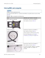
Page 193: ...r Cambium part number 30010195001 For 1 1 and 2 0 links order enough IF cable to connect two ODU CMU pairs at each link end Lightning protection unit LPU end kit Quantity per link 1 0 links 2 LPU kits 4 LPUs 1 1 Hot Standby links 4 LPU kits 8 LPUs 2 0 links 4 LPU kits 8 LPUs LPU END KIT PTP800 Cambium part number WB3657 Hoisting Grip for CNT 400 cable For hoisting the IF cable up to the ODU withou...

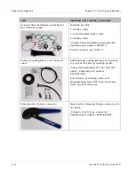
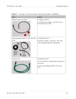
Page 194: ...it Cambium part number WB3616 For kit contents see Table 57 Cable grounding kits for 1 4 and 3 8 cable Additional grounding kits may be required to cover all IF cable grounding points Cable Grounding Kits For 1 4 And 3 8 Cable Cambium part number 01010419001 Kit contents grounding cable self amalgamating tape PVC tape tie wraps bolts washers and nuts Crimp tool for N type connector Required for cr...

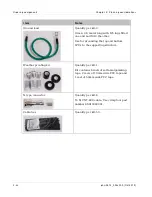
Page 195: ...tes Braided cable assembly Quantity per kit 1 0 7 meter long cable to go between the ODU and the top LPU Cable grounding kits for 1 4 and 3 8 cable Quantity per kit 2 Each kit contains earth wire PVC tape self amalgamating tape and fixings Ground lead Quantity per kit 1 Green 0 8 meter long with M5 lugs fitted each end Use for grounding the ODU to the top LPU ...

Page 196: ...ne end and M10 the other Use for grounding the top and bottom LPUs to the supporting structure Weather proofing kit Quantity per kit 1 Kit contains 6 reels of self amalgamating tape 2 reels of 19mm wide PVC tape and 1 reel of 50mm wide PVC tape N type connector Quantity per kit 4 To fit CNT 400 cable Use crimp tool part number 66010063001 Cable ties Quantity per kit 50 ...

Page 197: ...ium part num ber and notes ODU remote mounting kit Quantity per remote mounted ODU 1 Part numbers listed in Table 59 Flexible waveguide Quantity per remote mounted ODU 1 Part numbers listed in Table 60 All waveguides are 900 mm 35 in long For more information see Flexible waveguide specifications on page 4 10 Flex twist hanger kit Quantity per remote mounted ODU 2 Part numbers listed in Table 61 T...

Page 198: ... flexible waveguide Quantity per remote mounted ODU 1 Part number 58010077001 For more information see Flexible waveguide specifications on page 4 10 Table 5 9 Rem ote mounting kits Band Output Cam bium part num ber 6 GHZ UDR70 07010109008 7 GHz UBR84 07010109001 8 GHz UBR84 07010109002 11 13 GHZ UBR120 07010109003 15 GHz UBR140 07010109004 18 26 GHz UBR220 07010109005 28 32 GHz UBR320 07010109006...

Page 199: ...DR70 214 m E 102 mm 4 0 in H 204 mm 8 0 in 7 GHz 8 GHz 58010076019 0 4 dB m 1 10 PBR84 UDR84 264 m E 76 mm 3 0 in H 152 mm 6 0 in 11 GHz 13 GHz 58010076005 0 6 dB m 1 10 PBR120 UBR120 360 m E 64 mm 2 5 in H 115 mm 4 5 in 11 GHz 13 GHz 58010076018 PDR100 CPR90G 15 GHz 58010076008 0 99 dB m 1 10 PBR140 UBR140 445 m E 52 mm 2 in H 102 mm 4 in 18 GHz 23 GHz 26 GHz 58010076011 2 6 dB m 1 25 PBR220 UBR2...

Page 200: ...0118006 Ordering coupler mounting kits Applies to ODU deployments only Determine the number of coupler mounting kits required per link as follows 1 0 links not required 1 1 Hot Standby links without antenna protection 2 coupler mounting kits 1 1 Hot Standby links with antenna protection not required 2 0 co polar links 2 coupler mounting kits 2 0 cross polar links not required Select symmetric or a...

Page 201: ...ymmetric 07010110008 15 GHz 3 dB symmetric 07010110009 15 GHz 6 dB asymmetric 07010110010 18 GHz 3 dB symmetric 07010110011 18 GHz 6 dB asymmetric 07010110012 23 GHz 3 dB symmetric 07010110013 23 GHz 6 dB asymmetric 07010110014 26 GHz 3 dB symmetric 07010110015 26 GHz 6 dB asymmetric 07010110016 28 GHz 3 dB symmetric 07010110023 28 GHz 6 dB asymmetric 07010110024 32 GHz 3 dB symmetric 07010110017 ...

Page 202: ... same band as the antenna that it is upgrading for example use a 6 GHz OMK to upgrade a 6 GHz antenna Select OMKs from Table 63 Table 6 3 Orthogonal mounting kits OMKs Band Cam bium part num ber 6 GHz 85009316001 7 GHz and 8 GHz 85009316002 11 GHz 85009316004 13 GHz 85009316005 15 GHz 85009316006 18 GHz 85009316007 23 GHz 85009316008 Cambium also supply dual polar direct mount antennas complete wi...

Page 203: ...eployments Table 70 When ordering IRFUs specify the Tx and Rx center frequencies Table 6 4 IRFUs 6 GHz and 11 GHz Cam bium num ber Description 58009282002 IRFU ANSI 6G 1 0 HP 58009282013 IRFU ANSI 6G 1 0 MHSB Ready to upgrade to 1 1 EQ HP 58009282014 IRFU ANSI 6G 1 0 MHSB Ready to upgrade to 1 1 UNEQ HP 58009282005 IRFU ANSI 6G 1 1 EQ HP 58009282006 IRFU ANSI 6G 1 1 UNEQ HP 58009282004 IRFU ANSI 6...

Page 204: ... 58009281007 IRFU ANSI 11G 1 1 UNEQ 40MHz HP 58009281009 IRFU ANSI 11G 1 1 with SD 40MHz HP 58009281011 IRFU ANSI 11G 2 0 40MHz HP 58009281032 IRFU ANSI Side A 6G 1 0 HP and Side B 6G 1 0 HP 58009281030 IRFU ANSI Side A 6G 1 0 HP and Side B 11G 1 0 10 30 MHz HP 58009281031 IRFU ANSI Side A 6G 1 0 HP and Side B 11G 1 0 40 MHz HP 58009281027 IRFU ANSI Side A 11G 1 0 10 30 MHz HP and Side B 11G 1 0 1...

Page 205: ...ansceiver and BU 6 GHz and 11 GHz Cam bium num ber Description 30009399001 Cable Assembly Kit 1 SMA M M R A 30009399004 Cable Assembly Kit 2 SMA M M R A 30009399005 Cable Assembly Kit 3 SMA M M R A 30009399006 Cable Assembly Kit 4 SMA M M R A 30009399007 Cable Assembly Kit 5 SMA M M R A 30009399008 Cable Assembly Kit 6 SMA M M R A 30009399009 Cable Assembly Kit 7 SMA M M R A 30009399010 Cable Asse...

Page 206: ...009282009 IRFU ANSI 6G UNEQ HP 1 0 to 1 1 MHSB Upgrade Kit 58009282011 IRFU ANSI 6G HP 1 0 MHSB Ready to 1 1 MHSB Upgrade Kit 58009282012 IRFU ANSI 6G HP 1 0 MHSB Ready to 1 1 MHSB with SD Upgrade Kit 58009282010 IRFU ANSI 6G HP 1 0 to 1 1 MHSB with SD Upgrade Kit 58009281014 IRFU ANSI 11G EQ HP 1 0 to 1 1 MHSB Upgrade Kit 58009281015 IRFU ANSI 11G UNEQ HP 1 0 to 1 1 MHSB Upgrade Kit 58009281017 I...

Page 207: ...aveguide EWP52 and EWP63 07009344002 Hoisting Grip for waveguide EWP90 58009283001 Pressure Window for WR137 5 85 8 2 GHz mates to CPR137G 58009283002 Pressure Window for WR90 8 2 12 4 GHz mates to CPR90G 01009504002 DryLine Dehydrator Low pressure membrane Wall Mountable 115 Vac 58009284001 2 port Gas Distribution Manifold 58009284002 4 port Gas Distribution Manifold 58009279001 1 Flex Waveguide ...

Page 208: ...y network switch RJ45 connectors Two required per Cat5e cable Out of band protection splitter Quantity per link 2 with out of band management Only required for 1 1 links with out of band management 1 1 Out of Band Splitter Kit Cambium part number WB3807 Protection cable Quantity per link 2 with in band management Only required for 1 1 links with in band management For specification see Protection ...

Page 209: ... Standby link with out of band management Quantity per link 2 with out of band management 1 1 Optical Y Splitter Kit per end inc SFP Modules 850nm Cambium part number WB3806 Kit contains Two Optical Y cable assemblies one illustrated one for transmit and one for receive Two 1000 BASE SX SFP modules Ordering capacity upgrades Purchasing a capacity upgrade will not necessarily lead to an increase in...

Page 210: ...540 40 Mbps WB3541 50 Mbps WB3542 100 Mbps WB3543 150 Mbps WB3544 200 Mbps WB3545 300 Mbps WB3546 Full capacity Table 7 4 Step by step capacity upgrades per unit Cam bium part Capacity increase WB3547 20 Mbps 30 Mbps WB3548 30 Mbps 40 Mbps WB3549 40 Mbps 50 Mbps WB3550 50 Mbps 100 Mbps WB3551 100 Mbps 150 Mbps WB3552 150 Mbps 200 Mbps WB3553 200 Mbps 300 Mbps WB3554 300 Mbps full capacity ...

Page 211: ... not be made to the equipment without the express consent of the party responsible for compliance Any such modifications could void the user s authority to operate the equipment and will void the manufacturer s warranty The following topics are described in this section Cambium Networks end user license agreement on page 3 2 Hardware warranty on page 3 20 Limit of liability on page 3 21 ...

Page 212: ... TO THE TERMS OF THIS AGREEMENT Definitions In this Agreement the word Software refers to the set of instructions for computers in executable form and in any media which may include diskette CD ROM downloadable internet hardware or firmware licensed to you The word Documentation refers to electronic or printed manuals and accompanying instructional aids licensed to you The word Product refers to C...

Page 213: ...ept that you may either i make 1 copy of the transportable part of the Software which typically is supplied on diskette CD ROM or downloadable internet solely for back up purposes or ii copy the transportable part of the Software to a PC hard disk provided you keep the original solely for back up purposes If the Documentation is in printed form it may not be copied If the Documentation is in elect...

Page 214: ...e without Cambium s written consent Unauthorized copying of the Software or Documentation or failure to comply with any of the provisions of this Agreement will result in automatic termination of this license Confidentiality You acknowledge that all Software and Documentation contain valuable proprietary information and trade secrets and that unauthorized or improper use of the Software and Docume...

Page 215: ...tion and may be conditioned upon transferee paying all applicable license fees and agreeing to be bound by this Agreement Updates During the first 12 months after purchase of a Product or during the term of any executed Maintenance and Support Agreement for the Product you are entitled to receive Updates An Update means any code in any form which is a bug fix patch error correction or minor enhanc...

Page 216: ...TH RESPECT TO THE CORRECTNESS ACCURACY OR RELIABILITY OF THE SOFTWARE AND DOCUMENTATION Some jurisdictions do not allow the exclusion of implied warranties so the above exclusion may not apply to you Limitation of liability THE TOTAL LIABILITY OF CAMBIUM UNDER THIS AGREEMENT FOR DAMAGES WILL NOT EXCEED THE TOTAL AMOUNT PAID BY YOU FOR THE PRODUCT LICENSED UNDER THIS AGREEMENT IN NO EVENT WILL CAMB...

Page 217: ...at such terms and conditions are not inconsistent with the rights provided to you under the aforementioned provisions of the FAR and DFARS as applicable to the particular procuring agency and procurement transaction Term of license Your right to use the Software will continue in perpetuity unless terminated as follows Your right to use the Software will terminate immediately without notice upon a ...

Page 218: ...Agreement as necessary to comply with applicable laws Third party software The software may contain one or more items of Third Party Software supplied by other third party suppliers The terms of this Agreement govern your use of any Third Party Software UNLESS A SEPARATE THIRD PARTY SOFTWARE LICENSE IS INCLUDED IN WHICH CASE YOUR USE OF THE THIRD PARTY SOFTWARE WILL THEN BE GOVERNED BY THE SEPARAT...

Page 219: ...e contact openssl core openssl org 5 Products derived from this software may not be called OpenSSL nor may OpenSSL appear in their names without prior written permission of the OpenSSL Project 6 Redistributions of any form whatsoever must retain the following acknowledgment This product includes software developed by the OpenSSL Project for use in the OpenSSL Toolkit http www openssl org THIS SOFT...

Page 220: ...otice this list of conditions and the following disclaimer 2 Redistributions in binary form must reproduce the above copyright notice this list of conditions and the following disclaimer in the documentation and or other materials provided with the distribution 3 All advertising materials mentioning features or use of this software must display the following acknowledgement This product includes c...

Page 221: ...c written permission CMU AND THE REGENTS OF THE UNIVERSITY OF CALIFORNIA DISCLAIM ALL WARRANTIES WITH REGARD TO THIS SOFTWARE INCLUDING ALL IMPLIED WARRANTIES OF MERCHANTABILITY AND FITNESS IN NO EVENT SHALL CMU OR THE REGENTS OF THE UNIVERSITY OF CALIFORNIA BE LIABLE FOR ANY SPECIAL INDIRECT OR CONSEQUENTIAL DAMAGES OR ANY DAMAGES WHATSOEVER RESULTING FROM THE LOSS OF USE DATA OR PROFITS WHETHER ...

Page 222: ...ight notice this list of conditions and the following disclaimer Redistributions in binary form must reproduce the above copyright notice this list of conditions and the following disclaimer in the documentation and or other materials provided with the distribution The name of Cambridge Broadband Ltd may not be used to endorse or promote products derived from this software without specific prior w...

Page 223: ...AND FITNESS FOR A PARTICULAR PURPOSE ARE DISCLAIMED IN NO EVENT SHALL THE COPYRIGHT HOLDERS OR CONTRIBUTORS BE LIABLE FOR ANY DIRECT INDIRECT INCIDENTAL SPECIAL EXEMPLARY OR CONSEQUENTIAL DAMAGES INCLUDING BUT NOT LIMITED TO PROCUREMENT OF SUBSTITUTE GOODS OR SERVICES LOSS OF USE DATA OR PROFITS OR BUSINESS INTERRUPTION HOWEVER CAUSED AND ON ANY THEORY OF LIABILITY WHETHER IN CONTRACT STRICT LIABI...

Page 224: ...pyright notice this list of conditions and the following disclaimer Redistributions in binary form must reproduce the above copyright notice this list of conditions and the following disclaimer in the documentation and or other materials provided with the distribution Neither the name of Cisco Inc Beijing University of Posts and Telecommunications nor the names of their contributors may be used to...

Page 225: ...s brand or product names may not be used to endorse or promote products derived from this software without specific prior written permission THIS SOFTWARE IS PROVIDED BY THE COPYRIGHT HOLDER AS IS AND ANY EXPRESS OR IMPLIED WARRANTIES INCLUDING BUT NOT LIMITED TO THE IMPLIED WARRANTIES OF MERCHANTABILITY AND FITNESS FOR A PARTICULAR PURPOSE ARE DISCLAIMED IN NO EVENT SHALL THE COPYRIGHT HOLDER BE ...

Page 226: ...entity You or Your shall mean an individual or Legal Entity exercising permissions granted by this License Source form shall mean the preferred form for making modifications including but not limited to software source code documentation source and configuration files Object form shall mean any form resulting from mechanical transformation or translation of a Source form including but not limited ...

Page 227: ... the Work and such Derivative Works in Source or Object form 3 Grant of Patent License Subject to the terms and conditions of this License each Contributor hereby grants to You a perpetual worldwide non exclusive no charge royalty free irrevocable except as stated in this section patent license to make have made use offer to sell sell import and otherwise transfer the Work where such license appli...

Page 228: ...ms and conditions of this License without any additional terms or conditions Notwithstanding the above nothing herein shall supersede or modify the terms of any separate license agreement you may have executed with Licensor regarding such Contributions 6 Trademarks This License does not grant permission to use the trade names trademarks service marks or product names of the Licensor except as requ...

Page 229: ...r work To apply the Apache License to your work attach the following boilerplate notice with the fields enclosed by brackets replaced with your own identifying information Don t include the brackets The text should be enclosed in the appropriate comment syntax for the file format We also recommend that a file or class name and description of purpose be included on the same printed page as the copy...

Page 230: ...arrants that hardware will conform to the relevant published specifications and will be free from material defects in material and workmanship under normal use and service Cambium shall within this time at its own option either repair or replace the defective product within thirty 30 days of receipt of the defective product Repaired or replaced product will be subject to the original warranty peri...

Page 231: ... TO USE THE PRODUCT INCLUDING WITHOUT LIMITATION DAMAGES FOR LOSS OF BUSINESS PROFITS BUSINESS INTERRUPTION LOSS OF BUSINESS INFORMATION OR ANY OTHER PECUNIARY LOSS OR FROM ANY BREACH OF WARRANTY EVEN IF CAMBIUM HAS BEEN ADVISED OF THE POSSIBILITY OF SUCH DAMAGES Some states do not allow the exclusion or limitation of incidental or consequential damages so the above exclusion or limitation may not...

Page 232: ...Limit of liability Chapter 3 Legal information 3 22 phn 2513_004v000 Oct 2012 ...

Page 233: ...ing RF bands channel width and link loss Data network specifications on page 4 71 contains specifications of the PTP 800 Ethernet interface Syslog message formats on page 4 73 describes the format and content of Syslog event messages Network management specifications on page 4 77 lists supported SNMP objects from the standard MIB II IF MIB and Bridge MIB Electromagnetic compliance on page 4 82 des...

Page 234: ...The CMU and ODU power consumption figures are specified in Table 78 Table 7 5 CMU physical specifications Category Specification Dimensions Width 18 0 cm 7 1 in Height 3 5 cm 1 4 in Depth 22 0 cm 8 7 in Weight 1 1 kg 2 4 lbs Table 7 6 CMU environmental specifications Category Specification Temperature 33 C to 55 C Humidity 95 non condensing Waterproof IP20 UV Exposure 10 year operational life UL74...

Page 235: ...2 CMU W 1 0 Configuration W 1 1 Configuration W 6 29 46 20 66 115 7 29 46 20 66 115 8 29 46 20 66 115 11 23 46 20 66 109 13 10 35 20 55 85 15 10 35 20 55 85 18 7 35 20 55 82 23 14 35 20 55 89 26 14 35 20 55 89 28 13 35 20 55 88 32 19 35 20 55 94 38 21 35 20 55 96 1 Typical ODU DC power consumption in Mute condition W 2 Typical ODU DC power consumption in Transmit condition W ...

Page 236: ...e output 48 V dc nominal Maximum output power 80 W Line frequency 47 to 63 Hz Inrush current 40 A maximum at 264 V ac cold start 25 C Input current 1 8 A maximum Power conversion efficiency 85 typical Electromagnetic compatibility FCC Part 15 Subpart B Class A EN55022 CISPR 22 Class A Safety ground leakage current 3 5 mA maximum at 60 Hz 254 V ac input Hold up time 10 ms minimum at full load at 90...

Page 237: ... 33 C to 55 C cold start at 45 C Humidity 100 condensing Waterproof IP67 UV Exposure 10 year operational life UL746C test evidence RSSI output Table 82 specifies the voltage measured at the RSSI connector of the ODU for each combination of received signal level dBm and channel separation or bandwidth MHz This table applies to ODU A and ODU B Table 8 2 RSSI voltage received signal level and bandwid...

Page 238: ...06 4 14 4 00 30 3 90 4 00 4 08 3 94 31 3 84 3 93 4 01 3 87 32 3 78 3 87 3 95 3 81 33 3 71 3 81 3 89 3 75 34 3 65 3 74 3 82 3 68 35 3 59 3 68 3 76 3 62 36 3 52 3 62 3 70 3 56 37 3 46 3 55 3 63 3 49 38 3 40 3 49 3 57 3 43 39 3 33 3 43 3 51 3 37 40 3 27 3 36 3 44 3 30 41 3 21 3 30 3 38 3 24 42 3 14 3 24 3 32 3 18 43 3 08 3 17 3 25 3 11 44 3 02 3 11 3 19 3 05 45 2 95 3 05 3 13 2 98 46 2 89 2 98 3 06 2...

Page 239: ...2 36 2 22 58 2 13 2 22 2 30 2 16 59 2 07 2 16 2 24 2 10 60 2 00 2 10 2 17 2 03 61 1 94 2 03 2 11 1 97 62 1 88 1 97 2 05 1 91 63 1 81 1 90 1 98 1 84 64 1 75 1 84 1 92 1 78 65 1 69 1 78 1 86 1 72 66 1 62 1 71 1 79 1 65 67 1 56 1 65 1 73 1 59 68 1 50 1 59 1 67 1 53 69 1 43 1 52 1 60 1 46 70 1 37 1 46 1 54 1 40 71 1 31 1 40 1 48 1 34 72 1 24 1 33 1 41 1 27 73 1 18 1 27 1 35 1 21 74 1 11 1 21 1 29 1 15...

Page 240: ...0 29 0 38 0 46 0 32 88 0 23 0 32 0 40 0 26 89 0 16 0 26 0 34 0 19 90 0 10 0 19 0 27 0 13 IRFU specifications The PTP 800 IRFU conforms to the specifications in Table 83 Table 84 Table 85 and Table 86 and Table 87 Table 8 3 IRFU physical specifications Category Specification Rack mounting space RMS Less than 3 RMS 2 77 U in a NEBS standard 19 rack for an IRFU with 2 transceivers and associated BU D...

Page 241: ...Humidity Up to 95 non condensing Altitude 0 to 5000 m AMSL Vibration EN 300 019 2 3 class 3 2 Transit vibration packaged equipment EN 300 019 2 2 class 2 3 Transit shock packaged equipment EN 300 019 2 2 class 2 3 Earthquake EN 300 019 2 3 Table 8 6 IRFU EMC and safety compliance Category Specification Radiated and conducted susceptibility RF Magnetic field IEC 61000 4 3 Electrical Fast Transient ...

Page 242: ...nsum ption 4 8 V W 1 0 IRFU transceiver with fans operating 81 71 1 1 Active IRFU transceiver with fans operating 81 71 1 1 Inactive IRFU transceiver with fans off 68 8 60 5 Flexible waveguide specifications Waveguide flanges Figure 67 shows the locations of the flanges on the antenna transition waveguide and remote mounting kit RMK The numbers 1 to 4 refer to Table 88 Figure 6 7 Locations of wave...

Page 243: ...guide flange antenna 3 W aveguide flange ODU 4 RMK flange W ave guide size 6 GHz PDR70 n a UDR70 PDR70 UDR70 WR137 6 GHz CPR137G n a CPR137G PDR70 UDR70 WR137 7 GHz PDR84 n a UDR84 PBR84 UBR84 WR112 8 GHz PDR84 n a UDR84 PBR84 UBR84 WR112 11 GHz PDR100 UDR100 PBR120 UBR120 PBR120 UBR120 WR75 13 GHz PBR120 n a UBR120 PBR120 UBR120 WR75 15 GHz PBR140 n a UBR140 PBR140 UBR140 WR62 18 GHz PBR220 n a U...

Page 244: ...mation 4 12 phn 2513_004v000 Oct 2012 Waveguide flange diagrams Waveguide flanges are illustrated in Figure 68 Lower and Upper 6 GHz Figure 69 7 to 15 GHz Figure 70 18 to 38 GHz and Figure 71 11 GHz tapered transition Figure 6 8 Waveguide flanges 6 GHz ...

Page 245: ...PTP 800 Series User Guide Equipment specifications phn 2513_004v000 Oct 2012 4 13 Figure 6 9 Waveguide flanges 7 to 15 GHz ...

Page 246: ...Equipment specifications Chapter 4 Reference information 4 14 phn 2513_004v000 Oct 2012 Figure 7 0 Waveguide flanges 18 to 38 GHz Figure 7 1 Waveguide flanges 11 GHz tapered transition ...

Page 247: ...oupler mounting kits conform to the specifications listed in Table 90 and Table 91 Table 9 0 ODU coupler physical specifications Category Specification Packed dimensions 250 x 280 x 390 W x L x H mm 10 x 11 x 15 5 W x L x H ins Weight 6 GHz band 7 GHz to 11 GHz bands 4 6 kg 10 1 lbs 13 GHz to 38 GHz bands 4 2 kg 9 3 lbs Table 9 1 ODU coupler environmental specifications Category Specification Temp...

Page 248: ...ds ODU port return loss I solation betw een ODU ports 6 GHz 18 dB minimum 20 dB minimum 7 GHz to 38 GHz 20 dB maximum 20 dB minimum Table 93 contains ODU port insertion losses for Cambium supplied ODU couplers Table 9 3 ODU coupler insertion losses Bands Coupler type ODU port m axim um insertion losses 6 GHz 3 dB symmetric 6 dB asymmetric Main 1 9 dB Standby 6 5 dB 7 GHz to 26 GHz 3 dB symmetric 3...

Page 249: ...er specifications Category Specification Operating temperature range 33 C to 55 C Storage temperature range 40 C to 60 C Humidity 90 non condensing Compliance IEC 721 RoHS WEEE CMM Restrictions For indoor operation only Protection cable The maximum length of the protection cable is 2 meters The wiring must comply with one of the options given in Table 95 Table 9 5 Out of band protection cable pin ...

Page 250: ...conforms to the specifications listed in Table 96 Table 9 6 Fiber Y kit specifications Category Specification Operating mode 1000 BASE SX operating in Multi Mode with a wavelength of 850 nm Operating temperature range 33 C to 55 C Storage temperature range 40 C to 60 C Humidity 90 non condensing Compliance RoHS WEEE CMM Restrictions For indoor operation only ...

Page 251: ...cation Channel separation ETSI 7 13 75 14 27 5 28 29 65 30 40 55 56 or 60 MHz Channel bandwidth FCC IC 10 20 25 30 40 50 or 80 MHz Modulation QPSK 8PSK 16QAM 32QAM 64QAM 128QAM and 256QAM Fixed or adaptive modulation Duplex scheme Frequency division duplex Capacity options Basic capacity is 10 Mbps in each link direction May be upgraded via software license key to one of the following capacity lev...

Page 252: ... 40 60 340 14 02E F 384 10 7 14 340 7 GHz 7 1 7 9 7 14 28 154 161 168 196 245 02 06 Annex 1 and 3 F 385 9 8 GHz 7 7 8 5 7 14 28 119 126 208 266 F 386 8 An 2 3 5 29 65 311 32 F 386 8 An 6 11 GHz 10 7 11 7 40 490 530 12 06E F 387 10 13 GHz 12 75 13 25 7 14 28 266 12 02E F 497 7 15 GHz 14 4 15 35 7 14 28 56 420 490 644 728 T R 12 07 F 636 3 315 322 18 GHz 17 7 19 7 7 13 75 27 5 55 1010 12 03E F 595 9...

Page 253: ...147 o 10 1 08 Edition 18 GHz 17 7 18 7 10 20 30 40 50 ODU B 80 1560 FCC IC Part 101 147 r 10 1 08 Edition 23 GHz 21 8 23 6 10 20 30 40 50 1200 FCC IC Part 101 147 s 10 1 08 Edition 26 GHz 24 2 25 3 10 20 40 800 FCC only Part 101 147 s 10 1 08 Edition 38 GHz 38 6 40 10 50 700 FCC IC Table 1 0 0 FCC and IC band plan IRFU platforms Band Frequency range GHz Bandw idth MHz T R spacing MHz FCC I C Refer...

Page 254: ... maximum sustained aggregate load applied to the data and management Ethernet ports that can be delivered to the remote Ethernet ports without packet discard This capacity can be achieved with Ethernet Frames which have the highest configured Quality of Service class Capacity is approximately 1 5 lower for Ethernet Frames with a lower classification Please refer to Customer network on page 1 42 fo...

Page 255: ...or Minimum Transmit Power The tables are ordered by frequency band as follows Wireless performance in the Lower 6 GHz band ODU on page 4 24 Wireless performance in the Upper 6 GHz band ODU on page 4 26 Wireless performance in the 6 GHz band IRFU on page 4 29 Wireless performance in the 7 GHz band on page 4 32 Wireless performance in the 8 GHz band on page 4 33 Wireless performance in the 11 GHz ba...

Page 256: ...CM o dBm ACM i dBm Max tx dBm Min tx dBm 128QAM 0 83 Yes 50 7 74 1 69 67 5 22 9 64QAM 0 82 Yes 42 2 77 3 72 7 71 4 22 9 32QAM 0 87 Yes 34 7 79 3 74 9 73 6 22 9 16QAM 0 88 Yes 28 2 82 2 78 1 76 8 22 9 8PSK 0 86 Yes 20 8 84 5 79 9 78 6 22 9 QPSK 0 86 Yes 13 8 88 9 22 9 Table 1 0 4 Lower 6 GHz FCC and Canada with 30 MHz bandwidth Modulation m ode F R m ode Cap Mbps Sens dBm ACM o dBm ACM i dBm Max tx...

Page 257: ...ion m ode F R m ode Cap Mbps Sens dBm ACM o dBm ACM i dBm Max tx dBm Min tx dBm 256QAM 0 80 Yes 170 5 68 1 61 2 59 2 22 14 128QAM 0 84 Yes 151 1 70 9 67 5 66 3 24 14 64QAM 0 82 Yes 125 3 73 9 70 4 69 2 24 14 32QAM 0 85 Yes 101 2 76 4 73 2 71 9 28 14 16QAM 0 79 Yes 74 8 80 3 77 3 76 1 28 14 8PSK 0 80 No 56 8 79 77 8 28 14 QPSK 0 80 Yes 37 8 86 1 30 14 ...

Page 258: ...ACM o dBm ACM i dBm Max tx dBm Min tx dBm 128QAM 0 83 Yes 50 8 74 2 70 3 68 9 22 9 64QAM 0 83 Yes 42 8 77 3 73 6 72 4 22 9 32QAM 0 84 Yes 33 6 79 9 76 5 75 3 22 9 16QAM 0 91 Yes 29 1 82 4 79 2 78 22 9 8PSK 0 85 Yes 20 4 85 81 3 80 1 22 9 QPSK 0 86 Yes 13 8 89 9 22 9 Table 1 0 7 Upper 6 GHz FCC with 30 MHz bandwidth Modulation m ode F R m ode Cap Mbps Sens dBm ACM o dBm ACM i dBm Max tx dBm Min tx ...

Page 259: ... m ode F R m ode Cap Mbps Sens dBm ACM o dBm ACM i dBm Max tx dBm Min tx dBm 128QAM 0 76 Yes 71 73 4 68 6 67 2 24 14 64QAM 0 82 Yes 61 8 75 7 71 1 69 8 24 14 32QAM 0 87 Yes 50 7 77 7 73 4 72 1 26 14 16QAM 0 88 Yes 41 3 80 6 76 5 75 3 28 14 8PSK 0 86 No 30 4 78 3 77 28 14 QPSK 0 86 Yes 20 3 87 3 30 14 Table 1 1 0 Upper 6 GHz ETSI with 30 MHz channel separation Modulation m ode F R m ode Cap Mbps Se...

Page 260: ...2 No 150 7 70 7 69 5 26 14 16QAM 0 79 No 103 8 75 9 74 7 28 14 8PSK 0 80 No 78 9 77 6 76 3 28 14 QPSK 0 80 No 52 5 30 14 Table 1 1 2 Upper 6 GHz ETSI with 60 MHz channel separation Modulation m ode F R m ode Cap Mbps Sens dBm ACM o dBm ACM i dBm Max tx dBm Min tx dBm 256QAM 0 91 Yes 368 6 63 2 58 1 56 1 22 14 256QAM 0 80 Yes 347 1 65 1 58 1 56 1 22 14 128QAM 0 82 Yes 303 5 67 8 64 5 63 2 24 14 64Q...

Page 261: ... branching unit configuration which adds additional loss according to Table 116 The receive sensitivities are at the input to the IRFU transceiver and not at the waveguide interface The sensitivity at the waveguide interface depends on the branching unit configuration which adds additional loss according to Table 117 Table 1 1 3 6 GHz FCC and Canada with 10 MHz bandwidth for IRFU Modulation m ode ...

Page 262: ...es 90 6 78 72 70 7 32 10 16QAM 0 85 Yes 70 8 81 5 74 7 73 5 33 10 8PSK 0 81 Yes 50 8 83 9 78 5 77 2 33 10 QPSK 0 76 Yes 31 8 87 3 34 10 Table 1 1 5 6 GHz FCC and Canada with 30 MHz bandwidth for IRFU Modulation m ode F R m ode Cap Mbps Sens dBm ACM o dBm ACM i dBm Max tx dBm Min tx dBm 256QAM 0 80 Yes 177 4 68 6 61 5 59 4 29 10 128QAM 0 82 Yes 154 7 71 9 68 6 67 3 30 10 64QAM 0 88 Yes 135 9 74 1 7...

Page 263: ...l RFU 1plus1 MHSB Unequal RFU 1plus0 MHSB Ready Equal RFU 1plus0 MHSB Ready Unequal RFU 1plus1 Tx MHSB Rx SD 0 4 RFU 2plus0 0 0 5 Table 1 1 7 Receive branching unit losses for 6 GHz IRFU I RFU branching configuration Rx A BU loss Rx B BU loss RFU 1plus0 1 0 RFU 1plus1 MHSB Equal RFU 1plus0 MHSB Ready Equal 4 2 5 1 RFU 1plus1 MHSB Unequal RFU 1plus0 MHSB Ready Unequal 2 3 8 8 RFU 1plus1 Tx MHSB Rx ...

Page 264: ...Bm ACM o dBm ACM i dBm Max tx dBm Min tx dBm 128QAM 0 76 Yes 34 4 76 4 71 7 70 3 24 14 64QAM 0 82 Yes 30 78 8 74 2 72 9 24 14 32QAM 0 87 No 24 6 76 4 75 2 28 14 16QAM 0 88 Yes 20 83 7 79 6 78 3 28 14 8PSK 0 86 No 14 7 81 4 80 1 28 14 QPSK 0 88 Yes 10 90 4 30 14 Table 1 1 9 7 GHz ETSI with 14 MHz channel separation Modulation m ode F R m ode Cap Mbps Sens dBm ACM o dBm ACM i dBm Max tx dBm Min tx d...

Page 265: ...6 8 79 77 8 28 14 QPSK 0 80 Yes 37 8 86 1 30 14 Wireless performance in the 8 GHz band The following tables contain capacity transmit power and sensitivity data for PTP 800 links operating in the 8 GHz band For column definitions refer to Capacity transmit power and sensitivity on page 4 22 Table 1 2 1 8 GHz ETSI with 7 MHz channel separation Modulation m ode F R m ode Cap Mbps Sens dBm ACM o dBm ...

Page 266: ...s Sens dBm ACM o dBm ACM i dBm Max tx dBm Min tx dBm 256QAM 0 80 Yes 170 5 68 1 61 2 59 2 22 14 128QAM 0 84 Yes 151 1 70 9 67 5 66 3 24 14 64QAM 0 82 Yes 125 3 73 9 70 4 69 2 24 14 32QAM 0 85 Yes 101 2 76 4 73 2 71 9 28 14 16QAM 0 79 Yes 74 8 80 3 77 3 76 1 28 14 8PSK 0 80 No 56 8 79 77 8 28 14 QPSK 0 80 Yes 37 8 86 1 30 14 Table 1 2 4 8 GHz ETSI with 29 65 MHz channel separation Modulation m ode ...

Page 267: ... Mbps Sens dBm ACM o dBm ACM i dBm Max tx dBm Min tx dBm 128QAM 0 83 Yes 50 7 74 6 69 5 68 19 6 64QAM 0 82 Yes 42 2 77 8 73 2 71 9 19 6 32QAM 0 87 Yes 34 7 79 8 75 4 74 1 19 6 16QAM 0 88 Yes 28 2 82 7 78 6 77 3 19 6 8PSK 0 86 Yes 20 8 85 80 4 79 1 19 6 QPSK 0 86 Yes 13 8 89 4 19 6 Table 1 2 6 11 GHz FCC and Canada with 10 MHz bandwidth ODU B Modulation m ode F R m ode Cap Mbps Sens dBm ACM o dBm A...

Page 268: ...QAM 0 84 Yes 103 6 76 8 73 6 72 4 19 6 16QAM 0 79 Yes 77 9 80 6 77 6 76 4 19 6 8PSK 0 80 Yes 59 1 82 8 79 4 78 1 19 6 QPSK 0 80 Yes 39 4 86 4 19 6 Table 1 2 8 11 GHz FCC and Canada with 30 MHz bandwidth ODU B Modulation m ode F R m ode Cap Mbps Sens dBm ACM o dBm ACM i dBm Max tx dBm Min tx dBm 256QAM 0 80 Yes 177 4 68 1 61 58 9 20 5 128QAM 0 82 Yes 154 7 71 4 68 1 66 8 20 5 64QAM 0 88 Yes 135 9 7...

Page 269: ...AM 0 92 Yes 150 7 74 4 71 2 70 19 6 16QAM 0 79 Yes 103 8 79 3 76 4 75 2 19 6 8PSK 0 80 Yes 78 9 81 5 78 1 76 8 19 6 QPSK 0 80 Yes 52 5 85 1 19 6 Table 1 3 0 11 GHz FCC and Canada with 40 MHz bandwidth ODU B Modulation m ode F R m ode Cap Mbps Sens dBm ACM o dBm ACM i dBm Max tx dBm Min tx dBm 256QAM 0 80 Yes 236 6 67 1 60 1 58 1 20 5 128QAM 0 82 Yes 206 3 70 66 7 65 5 20 5 64QAM 0 87 Yes 180 72 5 ...

Page 270: ...ion Modulation m ode F R m ode Cap Mbps Sens dBm ACM o dBm ACM i dBm Max tx dBm Min tx dBm 256QAM 0 80 No 236 6 60 3 58 3 19 11 128QAM 0 82 Yes 206 8 69 9 66 6 65 4 21 11 64QAM 0 88 Yes 181 9 72 3 68 9 67 6 21 11 32QAM 0 92 No 150 7 71 2 70 26 11 16QAM 0 79 No 103 8 76 4 75 2 26 11 8PSK 0 80 No 78 9 78 1 76 8 26 11 QPSK 0 80 No 52 5 28 11 ...

Page 271: ...n the branching unit configuration which adds additional loss according to Table 135 The receive sensitivities are at the input to the IRFU transceiver and not at the waveguide interface The sensitivity at the waveguide interface depends on the branching unit configuration which adds additional loss according to Table 136 Table 1 3 2 11 GHz FCC and Canada with 10 MHz bandwidth for IRFU Modulation ...

Page 272: ...2QAM 0 83 Yes 102 6 77 2 74 72 8 29 7 16QAM 0 85 Yes 83 3 80 3 77 3 76 1 30 7 8PSK 0 80 Yes 58 9 82 6 79 2 77 9 30 7 QPSK 0 80 Yes 39 3 86 3 31 7 Table 1 3 4 11 GHz FCC and Canada with 40 MHz bandwidth for IRFU Modulation m ode F R m ode Cap Mbps Sens dBm ACM o dBm ACM i dBm Max tx dBm Min tx dBm 256QAM 0 80 Yes 236 6 67 1 60 1 58 1 26 7 128QAM 0 82 Yes 206 3 70 66 7 65 5 27 7 64QAM 0 87 Yes 180 7...

Page 273: ...l RFU 1plus1 MHSB Unequal RFU 1plus0 MHSB Ready Equal RFU 1plus0 MHSB Ready Unequal RFU 1plus1 Tx MHSB Rx SD 0 5 RFU 2plus0 0 0 7 Table 1 3 6 Receive branching unit losses for 11 GHz IRFU I RFU branching configuration Rx A BU loss Rx B BU loss RFU 1plus0 1 5 RFU 1plus1 MHSB Equal RFU 1plus0 MHSB Ready Equal 4 8 6 0 RFU 1plus1 MHSB Unequal RFU 1plus0 MHSB Ready Unequal 3 2 9 7 RFU 1plus1 Tx MHSB Rx...

Page 274: ... Sens dBm ACM o dBm ACM i dBm Max tx dBm Min tx dBm 128QAM 0 76 Yes 34 4 76 9 72 2 70 8 18 8 64QAM 0 82 Yes 30 79 3 74 7 73 4 18 8 32QAM 0 87 No 24 6 76 9 75 7 23 8 16QAM 0 88 Yes 20 84 2 80 1 78 8 23 8 8PSK 0 86 No 14 7 81 9 80 6 23 8 QPSK 0 88 Yes 10 90 9 26 8 Table 1 3 8 13 GHz ETSI with 14 MHz channel separation Modulation m ode F R m ode Cap Mbps Sens dBm ACM o dBm ACM i dBm Max tx dBm Min tx...

Page 275: ...ion m ode F R m ode Cap Mbps Sens dBm ACM o dBm ACM i dBm Max tx dBm Min tx dBm 256QAM 0 80 Yes 170 5 68 6 61 7 59 7 16 8 128QAM 0 84 Yes 151 1 71 4 68 66 8 18 8 64QAM 0 82 Yes 125 3 74 4 70 9 69 7 18 8 32QAM 0 85 Yes 101 2 76 9 73 7 72 4 23 8 16QAM 0 79 Yes 74 8 80 8 77 8 76 6 23 8 8PSK 0 80 No 56 8 79 5 78 3 23 8 QPSK 0 80 Yes 37 8 86 6 26 8 ...

Page 276: ... Sens dBm ACM o dBm ACM i dBm Max tx dBm Min tx dBm 128QAM 0 76 Yes 34 4 76 9 72 2 70 8 18 8 64QAM 0 82 Yes 30 79 3 74 7 73 4 18 8 32QAM 0 87 No 24 6 76 9 75 7 23 8 16QAM 0 88 Yes 20 84 2 80 1 78 8 23 8 8PSK 0 86 No 14 7 81 9 80 6 23 8 QPSK 0 88 Yes 10 90 9 26 8 Table 1 4 1 15 GHz ETSI with 14 MHz channel separation Modulation m ode F R m ode Cap Mbps Sens dBm ACM o dBm ACM i dBm Max tx dBm Min tx...

Page 277: ... 9 73 7 72 4 23 8 16QAM 0 79 Yes 74 8 80 8 77 8 76 6 23 8 8PSK 0 80 No 56 8 79 5 78 3 23 8 QPSK 0 80 Yes 37 8 86 6 26 8 Table 1 4 3 15 GHz ETSI with 56 MHz channel separation Modulation m ode F R m ode Cap Mbps Sens dBm ACM o dBm ACM i dBm Max tx dBm Min tx dBm 256 QAM 0 91 Yes 368 6 63 7 58 6 56 6 16 8 256 QAM 0 80 Yes 347 1 65 6 58 6 56 6 16 8 128 QAM 0 82 Yes 303 5 68 3 65 63 7 18 8 64 QAM 0 82...

Page 278: ...ACM o dBm ACM i dBm Max tx dBm Min tx dBm 128QAM 0 83 Yes 50 7 74 6 69 5 68 17 2 64QAM 0 82 Yes 42 2 77 8 73 2 71 9 17 2 32QAM 0 87 Yes 34 7 79 8 75 4 74 1 22 2 16QAM 0 88 Yes 28 2 82 7 78 6 77 3 22 2 8PSK 0 86 Yes 20 8 85 80 4 79 1 22 2 QPSK 0 86 Yes 13 8 89 4 23 2 Table 1 4 5 18 GHz FCC and Canada with 10 MHz bandwidth ODU B Modulation m ode F R m ode Cap Mbps Sens dBm ACM o dBm ACM i dBm Max tx...

Page 279: ...AM 0 84 Yes 67 8 78 3 74 8 73 5 22 2 16QAM 0 91 Yes 58 5 80 6 77 3 76 1 22 2 8PSK 0 83 Yes 40 3 83 6 79 8 78 6 22 2 QPSK 0 88 Yes 28 5 87 6 23 2 Table 1 4 7 18 GHz FCC and Canada with 20 MHz bandwidth ODU B Modulation m ode F R m ode Cap Mbps Sens dBm ACM o dBm ACM i dBm Max tx dBm Min tx dBm 256QAM 0 77 Yes 114 4 70 2 61 3 58 1 17 2 128QAM 0 83 Yes 102 72 7 69 67 7 19 2 64QAM 0 83 Yes 85 5 75 9 7...

Page 280: ...QAM 0 84 Yes 103 6 76 8 73 6 72 4 22 2 16QAM 0 79 Yes 77 9 80 6 77 6 76 4 22 2 8PSK 0 80 Yes 59 1 82 8 79 4 78 1 22 2 QPSK 0 80 Yes 39 4 86 4 23 2 Table 1 4 9 18 GHz FCC and Canada with 30 MHz bandwidth ODU B Modulation m ode F R m ode Cap Mbps Sens dBm ACM o dBm ACM i dBm Max tx dBm Min tx dBm 256QAM 0 80 Yes 177 4 68 1 61 58 9 17 2 128QAM 0 82 Yes 154 7 71 4 68 1 66 8 19 2 64QAM 0 88 Yes 135 9 7...

Page 281: ...AM 0 92 Yes 150 7 74 4 71 2 70 22 2 16QAM 0 79 Yes 103 8 79 3 76 4 75 2 22 2 8PSK 0 80 Yes 78 9 81 5 78 1 76 8 22 2 QPSK 0 80 Yes 52 5 85 1 23 2 Table 1 5 1 18 GHz FCC and Canada with 40 MHz bandwidth ODU B Modulation m ode F R m ode Cap Mbps Sens dBm ACM o dBm ACM i dBm Max tx dBm Min tx dBm 256QAM 0 80 Yes 236 6 67 1 60 1 58 1 17 2 128QAM 0 82 Yes 206 3 70 66 7 65 5 19 2 64QAM 0 87 Yes 180 72 5 ...

Page 282: ... 0 87 Yes 178 6 74 3 71 69 8 22 2 16QAM 0 91 Yes 150 5 76 3 73 3 72 22 2 8PSK 0 84 Yes 103 7 79 6 76 1 74 8 22 2 QPSK 0 80 Yes 65 7 84 2 23 2 Table 1 5 3 18 GHz FCC and Canada with 50 MHz bandwidth ODU B Modulation m ode F R m ode Cap Mbps Sens dBm ACM o dBm ACM i dBm Max tx dBm Min tx dBm 256QAM 0 83 Yes 302 1 65 8 58 5 56 3 17 2 128QAM 0 82 Yes 257 8 69 1 65 7 64 4 19 2 64QAM 0 82 Yes 216 5 72 1...

Page 283: ...1 83 5 24 2 Table 1 5 5 18 GHz ETSI with 7 MHz channel separation Modulation m ode F R m ode Cap Mbps Sens dBm ACM o dBm ACM i dBm Max tx dBm Min tx dBm 128QAM 0 76 Yes 34 4 76 9 72 2 70 8 17 7 64QAM 0 82 Yes 30 79 3 74 7 73 4 17 7 32QAM 0 87 No 24 6 76 9 75 7 22 7 16QAM 0 88 Yes 20 84 2 80 1 78 8 22 7 8PSK 0 86 No 14 7 81 9 80 6 22 7 QPSK 0 88 Yes 10 90 9 25 5 7 Table 1 5 6 18 GHz ETSI with 13 75...

Page 284: ... 76 9 73 8 72 5 22 7 16QAM 0 79 Yes 73 3 80 8 77 9 76 7 22 7 8PSK 0 80 No 55 7 79 6 78 4 22 7 QPSK 0 80 Yes 37 86 6 25 5 7 Table 1 5 8 18 GHz ETSI with 55 MHz channel separation Modulation m ode F R m ode Cap Mbps Sens dBm ACM o dBm ACM i dBm Max tx dBm Min tx dBm 256QAM 0 91 Yes 364 9 63 7 58 6 56 7 15 7 256QAM 0 80 Yes 343 6 65 6 58 6 56 7 15 7 128QAM 0 82 Yes 300 4 68 3 65 63 8 17 7 64QAM 0 82 ...

Page 285: ...m ode F R m ode Cap Mbps Sens dBm ACM o dBm ACM i dBm Max tx dBm Min tx dBm 256QAM 0 80 No 167 61 8 59 8 15 7 128QAM 0 84 Yes 148 71 4 68 1 66 9 17 7 64QAM 0 82 No 122 7 71 69 8 17 7 32QAM 0 85 No 99 1 73 8 72 5 22 7 16QAM 0 79 Yes 73 3 80 8 77 9 76 7 22 7 8PSK 0 80 No 55 7 79 6 78 4 22 7 QPSK 0 80 Yes 37 86 6 25 5 7 Table 1 6 1 18 GHz Brazil with 55 MHz channel separation Modulation m ode F R m o...

Page 286: ...ata for PTP 800 links operating in the 23 GHz band For column definitions refer to Capacity transmit power and sensitivity on page 4 22 Table 1 6 2 23 GHz FCC and Canada with 10 MHz bandwidth ODU A Modulation m ode F R m ode Cap Mbps Sens dBm ACM o dBm ACM i dBm Max tx dBm Min tx dBm 128QAM 0 83 Yes 50 7 74 1 69 67 5 17 2 64QAM 0 82 Yes 42 2 77 3 72 7 71 4 17 2 32QAM 0 87 Yes 34 7 79 3 74 9 73 6 2...

Page 287: ...9 76 5 75 3 23 2 16QAM 0 91 Yes 29 1 82 4 79 2 78 23 2 8PSK 0 85 Yes 20 4 85 81 3 80 1 23 2 QPSK 0 86 Yes 13 8 89 9 23 2 Table 1 6 4 23 GHz FCC and Canada with 20 MHz bandwidth ODU A Modulation m ode F R m ode Cap Mbps Sens dBm ACM o dBm ACM i dBm Max tx dBm Min tx dBm 256QAM 0 76 Yes 113 7 69 9 61 3 58 4 15 2 128QAM 0 83 Yes 102 2 72 68 2 66 9 17 2 64QAM 0 81 Yes 84 9 75 4 71 6 70 4 17 2 32QAM 0 ...

Page 288: ...QAM 0 85 Yes 68 8 77 9 74 4 73 1 23 2 16QAM 0 91 Yes 58 4 80 1 76 8 75 6 23 2 8PSK 0 83 Yes 40 4 83 2 79 4 78 2 23 2 QPSK 0 84 Yes 27 1 87 5 23 2 Table 1 6 6 23 GHz FCC and Canada with 30 MHz bandwidth ODU A Modulation m ode F R m ode Cap Mbps Sens dBm ACM o dBm ACM i dBm Max tx dBm Min tx dBm 256QAM 0 80 Yes 177 4 68 61 59 1 15 2 128QAM 0 82 Yes 155 1 70 7 67 4 66 1 17 2 64QAM 0 82 Yes 130 4 73 7...

Page 289: ... 83 Yes 102 6 76 7 73 5 72 3 23 2 16QAM 0 85 Yes 83 3 79 8 76 8 75 6 23 2 8PSK 0 80 Yes 58 9 82 1 78 7 77 4 23 2 QPSK 0 80 Yes 39 3 85 8 23 2 Table 1 6 8 23 GHz FCC and Canada with 40 MHz bandwidth ODU A Modulation m ode F R m ode Cap Mbps Sens dBm ACM o dBm ACM i dBm Max tx dBm Min tx dBm 256QAM 0 80 Yes 236 6 66 7 59 8 57 8 15 2 128QAM 0 82 Yes 206 8 69 4 66 1 64 9 17 2 64QAM 0 88 Yes 181 9 71 8...

Page 290: ... 92 Yes 150 4 73 9 70 7 69 5 23 2 16QAM 0 85 Yes 111 1 78 5 75 6 74 4 23 2 8PSK 0 80 Yes 78 5 80 8 77 4 76 1 23 2 QPSK 0 80 Yes 52 4 84 6 23 2 Table 1 7 0 23 GHz FCC and Canada with 50 MHz bandwidth ODU A Modulation m ode F R m ode Cap Mbps Sens dBm ACM o dBm ACM i dBm Max tx dBm Min tx dBm 256QAM 0 83 Yes 301 7 65 3 58 55 8 15 2 128QAM 0 82 Yes 258 6 68 5 65 1 63 8 17 2 64QAM 0 82 Yes 217 4 71 5 ...

Page 291: ...able 1 7 2 23 GHz ETSI with 7 MHz channel separation Modulation m ode F R m ode Cap Mbps Sens dBm ACM o dBm ACM i dBm Max tx dBm Min tx dBm 128QAM 0 76 Yes 34 4 76 4 71 7 70 3 17 2 64QAM 0 82 Yes 30 78 8 74 2 72 9 17 2 32QAM 0 87 No 24 6 76 4 75 2 22 2 16QAM 0 88 Yes 20 83 7 79 6 78 3 22 2 8PSK 0 86 No 14 7 81 4 80 1 22 2 QPSK 0 88 Yes 10 90 4 25 2 Table 1 7 3 23 GHz ETSI with 14 MHz channel separ...

Page 292: ... 101 2 76 4 73 2 71 9 22 7 16QAM 0 79 Yes 74 8 80 3 77 3 76 1 22 7 8PSK 0 80 No 56 8 79 77 8 22 7 QPSK 0 80 Yes 37 8 86 1 25 7 Table 1 7 5 23 GHz ETSI with 56 MHz channel separation Modulation m ode F R m ode Cap Mbps Sens dBm ACM o dBm ACM i dBm Max tx dBm Min tx dBm 256QAM 0 91 Yes 368 6 63 2 58 1 56 1 15 7 256QAM 0 80 Yes 347 1 65 1 58 1 56 1 15 7 128QAM 0 82 Yes 303 5 67 8 64 5 63 2 17 7 64QAM...

Page 293: ...x dBm Min tx dBm 128QAM 0 83 Yes 50 8 74 8 70 3 68 9 17 2 64QAM 0 83 Yes 42 8 77 8 73 5 72 3 17 2 32QAM 0 84 Yes 33 6 80 4 76 4 75 1 22 2 16QAM 0 91 Yes 29 1 82 9 79 1 77 9 22 2 8PSK 0 85 Yes 20 4 85 5 81 2 80 22 2 QPSK 0 86 Yes 13 8 90 4 23 2 Table 1 7 7 26 GHz FCC with 20 MHz bandwidth Modulation m ode F R m ode Cap Mbps Sens dBm ACM o dBm ACM i dBm Max tx dBm Min tx dBm 256QAM 0 76 Yes 113 7 69...

Page 294: ...1 7 9 26 GHz ETSI with 7 MHz channel separation Modulation m ode F R m ode Cap Mbps Sens dBm ACM o dBm ACM i dBm Max tx dBm Min tx dBm 128QAM 0 76 Yes 34 4 76 4 71 7 70 3 17 7 64QAM 0 82 Yes 30 78 8 74 2 72 9 17 7 32QAM 0 87 No 24 6 76 4 75 2 22 7 16QAM 0 88 Yes 20 83 7 79 6 78 3 22 7 8PSK 0 86 No 14 7 81 4 80 1 22 7 QPSK 0 88 Yes 10 90 4 25 7 Table 1 8 0 26 GHz ETSI with 14 MHz channel separation...

Page 295: ...1 2 76 4 73 2 71 9 22 7 16QAM 0 79 Yes 74 8 80 3 77 3 76 1 22 7 8PSK 0 80 No 56 8 79 77 8 22 7 QPSK 0 80 Yes 37 8 86 1 25 7 Table 1 8 2 26 GHz ETSI with 56 MHz channel separation Modulation m ode F R m ode Cap Mbps Sens dBm ACM o dBm ACM i dBm Max tx dBm Min tx dBm 256QAM 0 91 Yes 368 6 63 2 58 1 56 1 15 7 256QAM 0 80 Yes 347 1 65 1 58 1 56 1 15 7 128QAM 0 82 Yes 303 5 67 8 64 5 63 2 17 7 64QAM 0 ...

Page 296: ...ps Sens dBm ACM o dBm ACM i dBm Max tx dBm Min tx dBm 128QAM 0 76 Yes 34 4 75 9 71 2 69 8 17 7 64QAM 0 82 Yes 30 78 3 73 7 72 4 17 7 32QAM 0 87 No 24 6 75 9 74 7 20 7 16QAM 0 88 Yes 20 83 2 79 1 77 8 22 7 8PSK 0 86 No 14 7 80 9 79 6 22 7 QPSK 0 88 Yes 10 89 9 25 7 Table 1 8 4 28 GHz ETSI with 14 MHz channel separation Modulation m ode F R m ode Cap Mbps Sens dBm ACM o dBm ACM i dBm Max tx dBm Min ...

Page 297: ... 75 9 72 7 71 4 20 7 16QAM 0 79 Yes 74 8 79 8 76 8 75 6 22 7 8PSK 0 80 No 56 8 78 5 77 3 22 7 QPSK 0 80 Yes 37 8 85 6 25 7 Table 1 8 6 28 GHz ETSI with 56 MHz channel separation Modulation m ode F R m ode Cap Mbps Sens dBm ACM o dBm ACM i dBm Max tx dBm Min tx dBm 256QAM 0 91 Yes 368 6 62 7 57 6 55 6 15 7 256QAM 0 80 Yes 347 1 64 6 57 6 55 6 15 7 128QAM 0 82 Yes 303 5 67 3 64 62 7 17 7 64QAM 0 82 ...

Page 298: ...ns dBm ACM o dBm ACM i dBm Max tx dBm Min tx dBm 128QAM 0 76 Yes 34 4 75 4 70 7 69 3 16 6 64QAM 0 82 Yes 30 77 8 73 2 71 9 16 6 32QAM 0 87 Yes 24 6 79 8 75 4 74 2 19 6 16QAM 0 88 Yes 20 82 7 78 6 77 3 21 6 8PSK 0 86 No 14 7 80 4 79 1 21 6 QPSK 0 88 Yes 10 89 4 23 6 Table 1 8 8 32 GHz ETSI with 14 MHz channel separation Modulation m ode F R m ode Cap Mbps Sens dBm ACM o dBm ACM i dBm Max tx dBm Min...

Page 299: ... 75 4 72 2 70 9 19 6 16QAM 0 79 Yes 74 8 79 3 76 3 75 1 21 6 8PSK 0 80 No 56 8 78 76 8 21 6 QPSK 0 80 Yes 37 8 85 1 23 6 Table 1 9 0 32 GHz ETSI with 56 MHz channel separation Modulation m ode F R m ode Cap Mbps Sens dBm ACM o dBm ACM i dBm Max tx dBm Min tx dBm 256QAM 0 91 Yes 368 6 62 2 57 1 55 1 14 6 256QAM 0 80 Yes 347 1 64 1 57 1 55 1 14 6 128QAM 0 82 Yes 303 5 66 8 63 5 62 2 16 6 64QAM 0 82 ...

Page 300: ...tx dBm Min tx dBm 128QAM 0 83 Yes 50 8 71 8 67 3 65 9 16 1 64QAM 0 83 Yes 42 8 74 8 70 5 69 3 16 1 32QAM 0 84 Yes 33 6 77 4 73 4 72 1 20 1 16QAM 0 91 Yes 29 1 79 9 76 1 74 9 20 1 8PSK 0 85 Yes 20 4 82 5 78 2 77 20 1 QPSK 0 86 Yes 13 8 87 4 21 1 Table 1 9 2 38 GHz FCC and Canada with 50 MHz bandwidth Modulation m ode F R m ode Cap Mbps Sens dBm ACM o dBm ACM i dBm Max tx dBm Min tx dBm 256QAM 0 83 ...

Page 301: ... 9 16 6 32QAM 0 87 No 24 6 74 4 73 2 20 6 16QAM 0 88 Yes 20 81 7 77 6 76 3 20 6 8PSK 0 86 No 14 7 79 4 78 1 20 6 QPSK 0 88 Yes 10 88 4 23 6 Table 1 9 4 38 GHz ETSI with 14 MHz channel separation Modulation m ode F R m ode Cap Mbps Sens dBm ACM o dBm ACM i dBm Max tx dBm Min tx dBm 128QAM 0 76 Yes 71 71 4 66 6 65 2 16 6 64QAM 0 82 Yes 61 8 73 7 69 1 67 8 16 6 32QAM 0 87 No 50 7 71 4 70 1 20 6 16QAM...

Page 302: ... 101 2 74 4 71 2 69 9 20 6 16QAM 0 79 Yes 74 8 78 3 75 3 74 1 20 6 8PSK 0 80 No 56 8 77 75 8 20 6 QPSK 0 80 Yes 37 8 84 1 23 6 Table 1 9 6 38 GHz ETSI with 56 MHz channel separation Modulation m ode F R m ode Cap Mbps Sens dBm ACM o dBm ACM i dBm Max tx dBm Min tx dBm 256QAM 0 91 Yes 368 6 61 2 56 1 54 1 14 6 256QAM 0 80 Yes 347 1 63 1 56 1 54 1 14 6 128QAM 0 82 Yes 303 5 65 8 62 5 61 2 16 6 64QAM...

Page 303: ...ptions 100 Mbps Full Duplex Auto MDI MDIX Enabled when auto negotiation enabled Maximum frame size bytes 9600 Table 1 9 8 Fiber data port specifications Feature Specification Ethernet Speed 1000 Base SX or 1000 Base LX Requires upgrade kit Auto negotiation advertisement options 1000 Mbps Full Duplex Forced configuration options None Auto MDI MDIX Not applicable Maximum frame size bytes 9600 Table ...

Page 304: ... types Ethernet IEEE 802 3 2008 C VLAN IEEE 802 1Q 2005 S VLAN IEEE 802 1ad 2005 Service type Transparent Ethernet bridging equivalent to Ethernet private line EPL Service classes for bridged traffic Eight queues QoS Classification Layer 2 control protocols Bridge GARP MRP CFM R APS EAPS Layer 2 priority based on the priority code point PCP in the outermost VLAN tag Layer 3 priority based on IPv4 ...

Page 305: ...9 hos t na me 0 0 0 0 255 255 255 255 me s s a ge PTP800 CO SP c onf i gur a t i on s t a t us e ve nt c onf i gur a t i on c onf i gur a t i on SC SP a t t r i but e na me SC SP W e b us e r SNM P us e r SNTP SC SP wa s pr e vi ous va l ue SC SP now ne w va l ue SC s t a t us s t a t us SC SP a t t r i but e na me SC SP wa s pr e vi ous va l ue SC SP now ne w va l ue SC e ve nt e ve nt SC SP i de...

Page 306: ... warning 4 auth_login_failed security 4 warning 4 auth_login_locked security 4 info 6 auth_logout kernel 0 warning 4 cold_start PTP wireless bridge has reinitialized reason reset reason SC security 4 warning 4 License_update License Key updated SC syslog 5 warning 4 log_full Syslog local flash log is 90 full SC syslog 5 warning 4 log_wrap Syslog local flash log has wrapped SC local6 22 warning 4 p...

Page 307: ...SC kernel 0 warning 4 sys_reboot System Reboot reason reset reason SC security 4 warning 4 sys_software _upgrade Software upgraded from software version to software version SC software version 800 digit digit digit digit FIPS UCAPL SC local6 22 info 6 system_counters_reset System Counters Reset SC local6 22 info 6 system_statistics_reset System Statistics Reset SC local6 22 warning 4 telnet_idle T...

Page 308: ...r 4 Reference information 4 76 phn 2513_004v000 Oct 2012 Facility Severity I dentifier Message content NTP 12 warning 4 time_conn_failed SNTP connection failed at IP address IP address SC SP port number port SC SP reason reason SC ...

Page 309: ... e 1 3 6 1 2 1 1 1 sysDescr 1 3 6 1 2 1 1 2 sysObjectID 1 3 6 1 2 1 1 3 sysUpTime 1 3 6 1 2 1 1 4 sysContact 1 3 6 1 2 1 1 5 sysName 1 3 6 1 2 1 1 6 sysLocation 1 3 6 1 2 1 1 7 sysServices 1 3 6 1 2 1 2 1 ifNumber 1 3 6 1 2 1 2 2 1 1 ifIndex 1 3 6 1 2 1 2 2 1 2 ifDescr 1 3 6 1 2 1 2 2 1 3 ifType 1 3 6 1 2 1 2 2 1 4 ifMtu 1 3 6 1 2 1 2 2 1 5 ifSpeed 1 3 6 1 2 1 2 2 1 6 ifPhysAddress 1 3 6 1 2 1 2 2...

Page 310: ...3 6 1 2 1 31 1 1 1 3 ifInBroadcastPkts 1 3 6 1 2 1 31 1 1 1 4 ifOutMulticastPkts 1 3 6 1 2 1 31 1 1 1 5 ifOutBroadcastPkts 1 3 6 1 2 1 31 1 1 1 6 ifHCInOctets 1 3 6 1 2 1 31 1 1 1 7 ifHCInUcastPkts 1 3 6 1 2 1 31 1 1 1 8 ifHCInMulticastPkts 1 3 6 1 2 1 31 1 1 1 9 ifHCInBroadcastPkts 1 3 6 1 2 1 31 1 1 1 10 ifHCOutOctets 1 3 6 1 2 1 31 1 1 1 11 ifHCOutUcastPkts 1 3 6 1 2 1 31 1 1 1 12 ifHCOutMultic...

Page 311: ...perStatus 1 wireless interface propWirelessP2P 157 up down 2 ethernet data interface ethernetCsmacd 6 up down 3 ethernet management interface ethernetCsmacd 6 up down 4 telecom channel A interface ds1 18 notPresent 5 telecom channel B interface ds1 18 notPresent PTP 800 does not support telecom channels These interfaces are included for consistency with other Cambium PTP products Counters The tabl...

Page 312: ...ataRxBroadcastFrames ifInErrors EthernetDataRxFramesCRCError EthernetDataRxFramesUndersize EthernetDataRxFramesOversize ifInBroadcastPkts EthernetDataRxBroadcastFrames ifHCInOctets 64 bit version of ifInOctets ifHCInUcastPkts 64 bit version of ifInUcastPkts ifHCInBroadcastPkts 64 bit version of ifInBroadcastPkts ifOutOctets EthernetDataTxOctets ifOutUcastPkts EthernetDataTxFrames ifHCOutOctets 64 ...

Page 313: ...fOutUcastPkts EthernetManagementTxFrames EthernetManagementTxMulticastFrames EthernetManagementTxBroadcastFrames ifOutNUcastPkts EthernetManagementTxMulticastFrames EthernetManagementTxBroadcastFrames ifOutMulticastPkts EthernetManagementTxMulticastFrames ifOutBroadcastPkts EthernetManagementTxBroadcastFrames ifHCOutOctets 64 bit version of ifOutOctets ifHCOutUcastPkts 64 bit version of ifOutUcast...

Page 314: ...ied certificate to IEC 60950 EMC immunity compliance The PTP 800 has been tested for compliance to the EMC immunity specifications listed in Table 209 The top level Specification is ETSI 301 489 Table 2 0 9 EMC immunity compliance specifications Specification Com m ent EN 55082 1 Generic EMC and EMI requirements for Europe EN 61000 4 2 2001 Electro Static Discharge ESD Class 2 8 kV air 4 kV contact...

Page 315: ... applicable for Australia and New Zealand ETSI compliance testing The PTP 800 system has been tested for compliance to harmonized European standard EN 302 217 2 2 Digital systems operating in frequency bands where frequency coordination is applied This covers the essential requirements of Article 3 2 of the R TTE directive It has also been tested for compliance to the electro magnetic compatibilit...

Page 316: ...fication This equipment has been tested and found to comply with the limits for a Class A digital device pursuant to Part 15 of the FCC Rules and with RSS GEN of Industry Canada These limits are designed to provide reasonable protection against harmful interference when the equipment is operated in a commercial environment This equipment generates uses and can radiate radio frequency energy and if...

Page 317: ...rmation Hereby Cambium Networks declares that the PTP 800 product complies with the essential requirements and other relevant provisions of Directive 1999 5 EC The declaration of conformity may be consulted at the support web page see Contacting Cambium Networks on page 2 This equipment is marked to show compliance with the European R TTE directive 1999 5 EC Figure 7 2 European Union compliance la...

Page 318: ...al public EN 50383 2002 Basic standard for the calculation and measurement of electromagnetic field strength and SAR related to human exposure from radio base stations and fixed terminal stations for wireless telecommunication systems 110 MHz to 40 GHz Exposure categories EN 50385 2002 Clause 3 1 defines the restrictions on exposure to time varying electric magnetic and electromagnetic fields that...

Page 319: ...beamwidth degrees Rearranging terms to solve for distance yields δ πD S P d 180 Distances from antenna Table 210 specifies calculated minimum separation distances for a range of frequency bands and antenna sizes at the peak of the antenna beam At these and greater distances the power density from the RF field is not considered to be hazardous Table 2 1 0 PTP 800 minimum separation distances ETSI m...

Page 320: ...uating compliance in FCC OET Bulletin 65 Health Canada limits for the general population See the Health Canada web site at http www hc sc gc ca ewh semt pubs radiation 99ehd dhm237 limits limites_e html and Safety Code 6 ICNIRP International Commission on Non Ionizing Radiation Protection guidelines for the general public See the ICNIRP web site at http www icnirp de and Guidelines for Limiting Ex...

Page 321: ...and Antenna diam eter 0 3 m 1 ft 0 6 m 2 ft 0 8 m 2 5 ft 1 2 m 4 ft 1 8 m 6 ft 6 GHz 7 GHz 8 GHz N A N A N A 2 7 m 8 8 ft 4 2 m 13 6 ft 11 GHz N A 1 9 m 6 3 ft 2 7 m 8 9 ft 3 7 m 12 2 ft 5 6 m 18 4 ft 18 GHz 2 9 m 9 6 ft 4 8 m 15 8 ft 6 3 m 20 7 ft 9 6 m 31 5 ft 14 0 m 46 0 ft 23 GHz 3 0 m 9 9 ft 5 4 m 17 8 ft 7 1 m 23 3 ft 10 7 m 35 2 ft 14 9 m 48 9 ft 26 GHz 3 4 m 11 2 ft 5 9 m 19 4 ft 8 0 m 26 ...

Page 322: ...Radiation hazard assessm ent Chapter 4 Reference information 4 90 phn 2513_004v000 Oct 2012 ...

Page 323: ... the ODU LPUs and IF cable If installing or servicing an IRFU based link refer to Installing antennas and IRFUs on page 5 70 describes how to install an IRFU with antenna and waveguide Replacing IRFU components on page 5 95 describes how to to replace IRFU components in the field To install the CMU and network connections refer to Installing the CMU on page 5 77 describes how to mount the CMU in t...

Page 324: ...ed in Radiation hazard assessment on page 4 86 in particular the minimum separation distances Observe the following guidelines Never work in front of the antenna when the CMU is powered Always power down the CMU before connecting or disconnecting the drop cable from the CMU ODU or LPU Grounding and lightning protection requirements Ensure that the installation meets the requirements defined in Gro...

Page 325: ...principles described in Chapter 2 Planning considerations Check that the correct components are available as described Ordering components on page 2 57 Check the contents of all packages against their packing lists Preparing tools Check that the tools listed in Table 213 are available Table 2 1 3 Tools required for PTP 800 installation Equipm ent to be I nstalled Tools Required CMU Pozi screw driv...

Page 326: ...rque wrench Unit pre configuration To pre configure the CMUs during staging before site installation if this is required follow this process 1 Perform the following tasks from Chapter 6 Configuration and alignment for each CMU from Task 1 Connecting to the unit on page 6 3 to Task 11 Configuring remote access on page 6 96 2 Install and test the new hardware by following the relevant procedures in ...

Page 327: ... with two ODUs via coupler on page 5 20 1 1 Direct Yes Installing a direct mount antenna with one ODU on page 5 6 Repeat for the second antenna and ODU 1 1 Remote No Installing a remote mount antenna with two ODUs via coupler on page 5 26 1 1 Remote Yes Installing a remote mount antenna with one ODU on page 5 9 Repeat for the second antenna and ODU 2 0 co polar Direct Installing a direct mount ant...

Page 328: ...stalling 1 1 Hot Standby links observe that the ODUs are labeled Hi or Lo depending on the frequency sub band Install the two Hi ODUs at one end of the link and the two Lo ODUs at the other end Installing a direct mount antenna with one ODU In the direct mount configuration attach the ODU directly to the antenna with Cambium ODU interface via four latches To install a direct mount antenna with a s...

Page 329: ...7 3 Apply silicone grease to the O Ring of the antenna transition 4 Remove the ODU waveguide interface dust cover 5 Fit the ODU to the antenna transition ensuring that the antenna and ODU waveguide interfaces align correctly Observe the polarization of the antenna waveguide interface ...

Page 330: ...004v000 Oct 2012 6 Secure the ODU to the antenna with the four latches taking care to ensure they are correctly engaged 7 Check that the antenna mounting bracket and ODU are assembled 8 Follow the manufacturer s instructions to attach the assembly to the mast or pole ...

Page 331: ...e is installed in a stressed tensile condition keep vibration to a minimum as the waveguide rubber jacket may become more susceptible to ozone and general environmental attack Always use the waveguide hangers two hangers should be used for the 900mm 3ft flexible waveguide Bend radius Conform to the bend radii maximum twist and torque settings specified in Flexible waveguide specifications on page ...

Page 332: ...Installing antennas and ODUs Chapter 5 Installation 5 10 phn 2513_004v000 Oct 2012 Figure 7 3 Dual polar antenna in remote mount configuration ...

Page 333: ...ing ODU on pole using RMK To mount the ODU on the pole using a remote mounting kit RMK proceed as follows 1 Follow the manufacturer s instructions to attach the RMK to the mast or pole 2 Apply silicone grease to the O ring of the RMK transition 3 Remove the ODU waveguide interface dust cover ...

Page 334: ...513_004v000 Oct 2012 4 Fit the ODU to the RMK transition ensuring that the locating pegs on the RMK transition fit into the peg holes in the ODU waveguide interface 5 Secure the ODU to the RMK with the four latches taking care to ensure they are correctly engaged ...

Page 335: ...d on the mast or pole Assembling the flexible waveguide hangers To provide adequate support for a 900mm flexible waveguide install two hangers To assemble the flexible waveguide hangers proceed as follows 1 Check the flexible waveguide hanger kit contents 2 Assemble the pole clip making note of the angle of the slots in the metal strip ...

Page 336: ...Chapter 5 Installation 5 14 phn 2513_004v000 Oct 2012 3 Fit the rubber moulding clamp to the studding 4 Use the 5mm Allen key to fit the pole clip to the studding 5 Temporarily fit the rubber mouldings 6 Check the finished assembly ...

Page 337: ...t or pole 2 Check that the waveguide antenna and RMK have compatible interfaces Check that the mating surfaces are clean and free from damage 3 Fit one of the O ring seals supplied with the waveguide kit to the flexible waveguide flange that has the O ring groove 4 Using the waveguide flange fitted with the O ring fit the flexible waveguide to the remote mount Ensure that the waveguide cavity orie...

Page 338: ...flange of flexible waveguide to the antenna Ensure that the waveguide cavity orientation matches the opening in the antenna Secure the flexible waveguide using four of the shorter screws to the antenna Fit each screw with a spring washer and a plain washer 6 Fit the rubber inserts from the hanger kit to the flex waveguide 7 Insert the rubber insert and flex waveguide into the hanger ...

Page 339: ...P 800 Series User Guide Installing antennas and ODUs phn 2513_004v000 Oct 2012 5 17 8 Fit the hanger cover and tighten 9 When routing the flex waveguide ensure that the minimum bend radius is not exceeded ...

Page 340: ...uide When installing an 11 GHz remote mount antenna fit a tapered transition between the antenna and the flexible waveguide The tapered transition converts from the PDR100 waveguide flange on the antenna to the UBR120 flange on the flexible waveguide To mount an 11 GHz antenna with taper transition and flexible waveguide proceed as follows 1 Mount the bracket on the antenna ...

Page 341: ...Us phn 2513_004v000 Oct 2012 5 19 2 Remove the protective film from the antenna waveguide and fit the gasket supplied in the kit 3 Use the 8 screws to fit the tapered transition to the antenna 4 Fit the seal to the tapered transition supplied in the kit ...

Page 342: ...to water proof the junctions as shown Installing a direct mount antenna with two ODUs via coupler In the direct mount configuration attach the coupler with ODUs directly to the antenna with Cambium ODU interface via four latches If the coupler is asymmetric one side is embossed with the word MAIN and the other side with STANDBY Figure 74 The MAIN side has lower loss Ensure that the MAIN and STANDB...

Page 343: ...oupler asym metric shown Attaching coupler to antenna To attach the coupler to the antenna proceed as follows 1 Follow the antenna manufacturer s instructions to attach the antenna to its bracket 2 Check that the supplied coupler is the correct type for this installation Check the contents of the coupler mounting kit ...

Page 344: ... spacer length 7 75mm 4 For a 1 1 Hot Standby link check that the circular transitions on the coupler have the same alignment vertical or horizontal depending on the antenna polarity If necessary rotate the circular transitions according to the manufacturer s instructions 5 Take note of the word TOP embossed in the casting ensure this edge is upper most when attached to the antenna ...

Page 345: ... to the O Ring of the antenna transition 8 Fit the coupler to the antenna by following this sequence Initially hand tighten two of the diagonally opposed M8 bolts with the Allen key supplied in the kit Using the latch clamp clip the same two corners Repeat the above on the remaining two diagonally opposed bolts and clips Torque down all four M8 bolts to 18 Nm ...

Page 346: ...ctive film from the coupler ports 2 Apply silicone grease to the O rings of the coupler transitions 3 Fit the ODUs to the coupler transitions ensuring that the waveguide interfaces align correctly for vertical or horizontal polarization Fit both ODUs such that handles are at the top and connectors at the bottom For asymmetric couplers check that the MAIN and STANDBY sides of the coupler can still ...

Page 347: ...TP 800 Series User Guide Installing antennas and ODUs phn 2513_004v000 Oct 2012 5 25 4 Follow the manufacturer s instructions to attach the assembly to the mast or pole 5 Check the finished installation ...

Page 348: ...amination vibration or bending Observe the precautions in Installing a remote mount antenna with one ODU on page 5 9 Before installation check that the ODUs coupler RMK waveguide and antenna have compatible interfaces If the coupler is asymmetric one side is embossed with the word MAIN and the other side with STANDBY Figure 74 The MAIN side has lower loss Ensure that the MAIN and STANDBY sides can...

Page 349: ...004v000 Oct 2012 5 27 2 Check that the supplied coupler is the correct type for this installation Check the contents of the coupler mounting kit 3 Fit the correct spacers to each of the four legs 11GHz spacer length 27mm 18 GHz 23 GHz and 26 GHz spacer length 7 75mm ...

Page 350: ...orrectly aligned for remote mount bracket polarity vertical or horizontal If necessary rotate the circular transition according to the manufacturer s instructions 5 Take note of the polarization marks on the remote mount bracket 6 Take note of the word TOP embossed in the casting ensure this edge is upper most when attached to the antenna ...

Page 351: ...o the O ring of the remote mount transition 9 Fit the coupler to the remote mount bracket by following this sequence Initially hand tighten two of the diagonally opposed M8 bolts with the Allen Key supplied in the kit Using the latch clamp clip the same two corners Repeat the above on the remaining two diagonally opposed bolts and clips Torque down all four M8 bolts to 18Nm ...

Page 352: ...ing the flexible waveguide hangers on page 5 13 Attaching antenna to pole Follow the antenna manufacturer s instructions to attach the antenna to its bracket and to the mast or pole Attaching ODUs to coupler remote To attach the ODUs to the coupler and mount the assembly on the pole proceed as follows 1 Fit the flex waveguide to the remote mount bracket 2 Fit assembly to pole ...

Page 353: ...5 Apply silicone grease to the O rings of the coupler transitions 6 Fit the ODUs to the coupler transitions ensuring that the waveguide interfaces align correctly for vertical or horizontal polarization Fit both ODUs such that handles are at the top and connectors at the bottom For asymmetric couplers check that the MAIN and STANDBY sides of the coupler can still be identified ...

Page 354: ...nas and ODUs Chapter 5 Installation 5 32 phn 2513_004v000 Oct 2012 7 Support the flexible waveguide with the waveguide hangers Do not exceed the flexible waveguide minimum bend radius 8 Check the finished installation ...

Page 355: ...ansducer with two direct mount interfaces To upgrade any standard antenna to a direct mount dual polar antenna purchase an orthogonal mount kit OMK from Cambium To install a direct mount dual polar antenna with two ODUs proceed as follows 1 Follow the manufacturer s instructions to fit the antenna mounting bracket and fit the antenna to the orthogonal mode transducer 2 Remove protective film from ...

Page 356: ...2012 3 Apply silicone grease to the O rings of the ODU transitions 4 Fit the ODUs to the transitions ensuring that the waveguide interfaces align correctly for vertical or horizontal polarization 5 Follow the manufacturer s instructions to attach the assembly to the mast or pole ...

Page 357: ... Series User Guide Installing antennas and ODUs phn 2513_004v000 Oct 2012 5 35 6 Place the supplied spirit level on the leveling flat and use it to achieve horizontal alignment of the antenna and ODU assembly ...

Page 358: ...lling and grounding the main IF cable on page 5 52 Making an IF cable ground point on page 5 54 Installing and grounding the IF cable at building entry on page 5 58 To avoid damage to equipment observe the following precautions when installing IF and ground cables When installing IF and ground cables observe the following precautions o Ensure that the IF and ground cable installation meets the req...

Page 359: ...PTP 800 Series User Guide Installing the IF and ground cables phn 2513_004v000 Oct 2012 5 37 Figure 7 5 Correct orientation of LPUs ...

Page 360: ...g grips onto the top end of the main IF cable as described in Hoisting the main IF cable on page 5 49 o Fit an N type connector to the top end only as described in Fitting an N type connector to an IF cable on page 5 38 LPU CMU IF cable Prepare a short section of IF cable to connect the bottom LPU to the CMU o Cut this to the approximate length required allowing a bit of surplus o Fit an N type co...

Page 361: ...4v000 Oct 2012 5 39 2 Remove 21mm 0 827 inch of the outer jacket 3 Slide ferrule over braid ensure the chamfer is towards the braid 4 Comb braid straight with wire brush 5 Trim braid back to 9mm 0 354 inch 6 Remove foam insulation and trim centre conductor to 6mm 0 236 inch ...

Page 362: ...v000 Oct 2012 7 Chamfer the centre conductor at a angle of 45 Failure to correctly chamfer the centre conductor will cause damage to the connector when assembling the cable into the connector 8 Mark a line 22 mm from the end of the ferrule 9 Daub grease onto the braid uniformly ...

Page 363: ...ctor to an IF cable proceed as follows 1 Insert the cable into connector The cable centre conductor must be inserted into the inner contact fingers 2 Ensure that the cable is not inserted beyond the line marked in Step 8 Crimp the connector body in the area shown 3 Use the larger of the openings in the crimp tool 4 Check the finished part ...

Page 364: ...LPU Perform this procedure to connect the ODU to the top lightning protection unit LPU via ground and IF cables and to ground the LPU to the supporting structure Figure 76 Figure 7 6 ODU and top LPU grounding To connect and ground the ODU and top LPU proceed as follows 1 Attach one end of the ODU ground cable to the ODU ...

Page 365: ... cables phn 2513_004v000 Oct 2012 5 43 2 Attach the other end of the ODU ground cable to the top LPU under the LPU mounting nut Attach one end of the LPU ground cable to the LPU under the LPU mounting nut 3 Attach one end of the ODU LPU IF cable to the ODU ...

Page 366: ... ODU LPU IF cable to the EQUIPMENT port of the top LPU 5 Mount the top LPU on the supporting structure 6 Route and fasten the ODU ground cable and ODU LPU IF cable The ground cable should be routed downwards without any loops 7 Attach the other end of the LPU ground cable to the grounding bar of the supporting structure ...

Page 367: ...ation has been tested as described in Testing the ODU and IF cable on page 5 60 These tests require connection and disconnection of the IF cables at various places Tighten N type connectors using a torque wrench set to 1 7 Nm 15 lb in If a torque wrench is not available finger tighten the N type connectors To weatherproof an N type connector proceed as follows 1 Ensure the connection is tight usin...

Page 368: ...er 5 Installation 5 46 phn 2513_004v000 Oct 2012 3 Smooth tape edges 4 Cut a 125mm 5 inches length of rubber tape self amalgamating 5 Expand the width of the tape by stretching it so that it will wrap completely around the connector and cable ...

Page 369: ...ct 2012 5 47 6 Press the tape edges together so that there are no gaps The tape should extend 25mm 1inch beyond the PVC tape 7 Wrap a layer of 50 mm 2 inch PVC tape from bottom to top starting from 25 mm 1 inch below the edge of the self amalgamating tape overlapping at half width ...

Page 370: ...ers of 19 mm 0 75 inch PVC tape always overlapping at half width Wrap the layers in alternate directions Second layer top to bottom Third layer bottom to top Fourth layer top to bottom Fifth layer bottom to top The bottom edge of each layer should be 25 mm 1 inch below the previous layer 9 Completed weatherproof connection ...

Page 371: ...pting to hoist more than one cable may cause the hoisting grip to break or the cables to fall Do not use the hoisting grip for lowering cable unless the clamp is securely in place Do not reuse hoisting grips Used grips may have lost elasticity stretched or become weakened Reusing a grip can cause the cable to slip break or fall Use hoisting grips at intervals of no more than 60 m 200 ft Use the pr...

Page 372: ... hoisting grip s at the proper location on the cable before attaching the connector Allow a sufficient length of cable leader to reach the antenna connector when cable hoisting and attachment of the grip handle is completed Hold the heel with one hand and firmly slide the other hand along the grip to tighten it 2 Slide the clamp onto the grip and position it 25 mm 1 from the heel 3 Crimp the clamp...

Page 373: ...er Also do not release tension on the grip until after the cable has been fastened to the tower members Attach the hoist line to the grip Figure 77 Tie the cable leader to the hoist line so that the leader does not dangle Apply tension slowly to the hoist line allowing the hoisting grip to tighten uniformly on the cable Hoist the main IF cable up to the ODU Figure 7 7 Using the hoist line When the...

Page 374: ...ding the main IF cable Perform this procedure to install and ground the IF cable from the top LPU to the building entry point Figure 78 The IF cable must be grounded at the points specified in Protection requirements for a mast or tower installation on page 2 11 Figure 7 8 IF cable grounding on a mast or tower ...

Page 375: ...ing self amalgamating and PVC tape as described in Weatherproofing an N type connector on page 5 45 3 Lay the main IF cable as far as the building entry point ensuring there is enough length to extend through the wall of the building to the bottom LPU 4 Attach the main IF cable to the supporting structure using the cable ties provided 5 Ground the IF cable at the points specified in Protection req...

Page 376: ... 8 cable Figure 26 contains the following components 1 x grounding cable with grounding 2 hole lug fitted M10 1 x self Amalgamating tape 1 x PVC tape 3 x tie wraps 2 x bolt washer and nut Install ground cables installed without drip loops and pointing down towards the ground otherwise they may not be effective To ground the IF cable to a metal structure using the Cambium grounding kit part number ...

Page 377: ... 55 2 Cut 38 mm 1 5 inches of rubber tape self amalgamating and fit to the ground cable lug Wrap the tape completely around the lug and cable 3 Fold the ground wire strap around the drop cable screen and fit cable ties 4 Tighten the cable ties with pliers Cut the surplus from the cable ties ...

Page 378: ... Cut a 38 mm 1 5 inches section of self amalgamating tape and fit to the ground cable lug Wrap the self amalgamating tape completely around the lug and cable 6 Use the remainder of the self amalgamating tape to wrap the complete assembly Press the tape edges together so that there are no gaps ...

Page 379: ... tape always overlapping at half width Wrap the layers in alternate directions Second layer top to bottom Third layer bottom to top Fourth layer top to bottom Fifth layer bottom to top The edges of each layer should be 25mm 1 inch above A and 25 mm 1 inch below B the previous layer 9 Prepare the metal grounding point of the supporting structure to provide a good electrical contact with the groundi...

Page 380: ...orting structure using site approved methods Use a two hole lug secured with fasteners in both holes This provides better protection than a single hole lug Installing and grounding the IF cable at building entry Perform this procedure to install and ground the IF at the building or cabinet entry point Figure 79 Figure 7 9 Grounding at building entry ...

Page 381: ...as described in Making an IF cable ground point on page 5 54 3 Install the bottom LPU inside the building entry point 4 Ground the bottom LPU to the master ground bar 5 Cut any surplus length from the bottom end of the main IF cable and fit an N type connector as described in Fitting an N type connector to an IF cable on page 5 38 6 Connect the main IF cable from the ODU to the SURGE port of the b...

Page 382: ...Confirm that the cable contains no short circuit or open circuit Distance to fault DTF return loss with the ODU connected Confirm the position of the LPUs in the cable run and confirm that there are no other points of discontinuity in the cable To detect any degradation over time compare a current plot to a previously recorded plot if available Test equipment Use an RF cable analyzer such as an An...

Page 383: ...w how this is done In this example there is a short length of cable from the analyzer in place of the CMU to the first LPU a length of cable y from the first LPU to the second LPU at the top of the tower and a short length of cable from the second LPU to the ODU 0 7m long supplied in the accessory kit Figure 8 1 Example of the cable test Perform these tests in conjunction with the test equipment m...

Page 384: ...escribed in Test preparation on page 5 61 To measure cable loss proceed as follows 1 Select the cable loss one port mode of the cable analyzer Figure 80 2 Set the frequency of measurement to F1 350MHz F2 400MHz 3 Calibrate the instrument for the selected frequencies using the correct calibration kit 4 Before connecting the ODU obtain a plot of cable loss and check that it is within the expected li...

Page 385: ...le from the LPU to ODU When performing steps 4 to 6 above compare the before and after plots of cable loss Figure 82 is a plot of cable loss taken before the ODU was connected The plot shows an average cable loss of 1 96 dB This can be compared with the expected result in Table 215 For a cable length of approximately 19m 17m 0 7m 0 7m with two LPUs the table result is 1 9 dB which is within the ex...

Page 386: ... ODU connected Cable loss example using a 100 meter cable This is similar to the above example except that there is now 100m of cable between the two LPUs length y in Figure 81 It shows similar results Figure 84 is a plot of cable loss taken before the ODU was connected Figure 85 is a plot of cable loss taken after the ODU was connected ...

Page 387: ... Series User Guide Testing the ODU and IF cable phn 2513_004v000 Oct 2012 5 65 Figure 8 4 Cable loss plot for a 100 m eter cable with no ODU Figure 8 5 Cable loss plot for a 100 m eter cable with ODU connected ...

Page 388: ... for example 1 76 dB means that the loss is expected to be between 1 58 and 1 94 dB Table 2 1 5 Expected cable loss when ODU is not connected Cable Length m eters Cable Loss 1 0 at 3 5 0 MHz dB Cable Loss 1 0 w ith tw o Lightning Protection Units fitted at 3 5 0 MHz dB 1 0 08 0 3 2 0 15 0 37 3 0 23 0 45 4 0 31 0 53 5 0 39 0 61 6 0 46 0 68 7 0 54 0 76 8 0 62 0 84 9 0 69 0 91 10 0 77 0 99 20 1 54 1 ...

Page 389: ...e following Cable type select LMR400 similar to CNT 400 or LMR600 similar to CNT 600 as appropriate F2 select the highest frequency possible for the greatest resolution 1600 MHz D1 and D2 set as appropriate for the specific installation 4 Recalibrate the instrument 5 Before connecting the ODU obtain a plot of DTF loss Compare it to an example of a good installation Figure 86 6 Connect the ODU 7 Ob...

Page 390: ...shown The cable between them shows no discontinuity There are two plots Figure 86 is a plot of DTF return loss before the ODU is connected The final peak marker M1 is the position of the cable open circuit Figure 87 is a plot of DTF return loss after the ODU is connected The final peak remains in the same position but is now reduced in amplitude because less signal is reflected as a consequence of...

Page 391: ...PTP 800 Series User Guide Testing the ODU and IF cable phn 2513_004v000 Oct 2012 5 69 Figure 8 7 DTF plot for a 17 m eter cable with ODU connected ...

Page 392: ...e provided IF cable for CMU and IRFU Cambium part number 30009403001 A 48 V dc power source Access to the building ground terminal All required tools Table 216 Table 2 1 6 Tools required for IRFU installation I tem Required specifications W here used Screwdriver Phillips 2 medium tip Throughout Allen key For 8 32 socket head screws For connecting the flexible waveguide to the IRFU Multimeter With ...

Page 393: ...en two IRFU shelves Mounting brackets can be assembled for either ETSI or NEBS ANSI rack mounting To minimize risk of injury use two persons to place a fully assembled IRFU weighing approximately 12 kg in the rack Install the shelf mounting lugs 2 using the machine screws provided Leave these lugs in place for holding the IRFU during installation Starting with the two top screws secure the six mou...

Page 394: ...veguide to its mating flange on the BU using the eight socket head screws provided Refer to Table 217 for the waveguide and flange specifications 3 Install the correct flange gasket according to the type of waveguide mating flange not supplied 4 Check that the waveguide has been installed according to manufacturer s instructions with sealed ends and a pressure window 5 Pressurize the waveguide wit...

Page 395: ...e type Flange holes L6 and U6 WR 137 CPR 137G Tapped for 8 32 screws 7 and 8 WR 112 CPR 112G 11 WR 90 CPR 90G Connecting the CMU cables to the IRFU Connect the CMU to the IRFU using the supplied IF cable Cambium part number 30009403001 Figure 90 For 1 1 and 2 0 links repeat for the second transceiver unit and CMU Figure 9 0 Connecting the coaxial cable to the IRFU ...

Page 396: ...rounding the IRFU Ground the IRFU by connecting a 4 11 mm 6 AWG copper cable from any one of the grounding terminals of the IRFU shelf Figure 91 and Figure 92 to the building grounding system Figure 9 1 IRFU grounding terminal front option Figure 9 2 IRFU grounding terminal rear option ...

Page 397: ...ct other equipment to the same grounding cable as the IRFU Each piece of equipment at the site should have a separate grounding cable to a common very low resistance main ground point Connect the equipment directly to the DC supply system grounding electrode conductor or to a bonding jumper from a grounding terminal bar or bus to which the DC supply grounding electrode is connected Provide fusing ...

Page 398: ...ower connector screws are tight enough to hold the power cable securely in place For EMI Class B compliance a 10 AWG braided shielded power cable with drain wire and foil is recommended If a battery is being used to supply power connect the common battery terminal to the main electrical grounding system not directly to the building grounding system Figure 9 3 IRFU power connection ...

Page 399: ... CMU on either a horizontal or vertical surface using the supplied mounting bracket Do not operate the CMU in ambient temperatures exceeding 40 deg C unless mounted in a Restricted Access Location At ambient temperatures over this limit the temperature of the external metal case parts of the CMU may exceed a touch temperature of 70 deg C Heat warning labels are fixed adjacent to the hottest parts ...

Page 400: ...MU Mount the CMU in one of three ways On a shelf or bench top On a wall In a cabinet rack The CMU kit contains the CMU CMU bracket power connector and ground lug Figure 94 Figure 9 4 CMU kit contents To prevent the CMU from overheating ensure that the ventilation holes on the side of the CMU are not obstructed and that there is room for air flow across the back of the CMU the end opposite the conn...

Page 401: ...the CMU using the screws supplied before offering the assembly up to the wall for fixing In order to comply with safety certification mount the CMU with the connectors facing upwards or downwards do not mount the CMU with the connectors facing sideways Figure 9 6 CMU mounted with bracket Rack mounting When moutning in a 19 inch cabinet rack use a rack mounting kit Figure 97 and Figure 98 This can ...

Page 402: ...cable is always exceeded If cables are laid in an air handling cavity they must be Plenum rated Grounding the CMU Ground the CMU to a rack ground bar master ground bar or other suitable ground using a minimum cable cross section of 10 mm2 6AWG Figure 43 It is a condition of the safety approval that the unit is grounded For a 1 1 Hot Standby link ground both CMUs to the same grounding point Figure ...

Page 403: ...012 5 81 Figure 9 9 CMU ground connector Connecting the CMU to the IF cable If space inside the cabinet is limited install a right angle IF cable connector Cambium part number 01010589001 Figure 100 Figure 1 0 0 Rack m ounted CMU with a right angled IF cable connector ...

Page 404: ...upler to the CMU labelled Secondary IRFU based deployments Connect the supplied IF cable Cambium part number 30009403001 to the CMU For 1 1 and 2 0 links repeat for the second transceiver unit and CMU For an IRFU based 1 1 Hot Standby link with the unequal coupling option make the following connections 1 Connect the IF cable from the primary left hand transceiver to the CMU labelled Primary 2 Conn...

Page 405: ...supply is to be installed ensure that it meets the following safeguards The DC supply has over current protection that does not exceed 3 amps There is a way to isolate the CMU from the DC supply If a DC connector has to be attached to the DC output cable use the following pin connections Pin 1 48 Volts Pin 2 0 Volts Pin 3 Not Connected Pin 4 Chassis ground Pin 1 is the left most pin on the CMU pow...

Page 406: ...g a 2 0 link prepare separate network connections for the link A and the link B CMUs The CMU is not normally connected to the network equipment until antenna alignment is complete as described in Task 15 Connecting link to the network on page 6 114 For all management modes out of band and in band decide whether the data network connection is to be copper or fiber then perform either Installing a c...

Page 407: ...and 2 0 links phn 2513_004v000 Oct 2012 5 85 Installing a copper data interface If an unprotected configuration requires a copper data interface connect the CMU Data port copper to the network as shown in Figure 102 Figure 1 0 2 Copper data interface connections ...

Page 408: ...4v000 Oct 2012 Installing a fiber data interface If an unprotected configuration requires a fiber data interface connect the CMU Fiber SFP GigE port to the network as shown in Figure 103 Figure 1 0 3 Fiber data interface connections Refer to Connecting fiber cables to the CMU on page 5 88 ...

Page 409: ...anagement interface If an unprotected configuration requires a management interface connect the CMU Management port to the network as shown in Figure 104 At the edge of a network if the management network equipment is inaccessible leave the CMU management port disconnected Figure 1 0 4 Managem ent interface connections ...

Page 410: ...Connecting fiber cables to the CMU To connect fiber cables to the CMU proceed as follows 1 Insert an SFP module into the GigE port of the CMU with the PCB connector down and label up 2 Remove the protective caps from the LC connectors 3 Plug the LC connectors into the SFP module ensuring they snap home ...

Page 411: ...a redundant copper interface on page 5 91 Or Installing a redundant fiber interface on page 5 92 Or one copper and one fiber 1 Or Installing a Fiber Y interface on page 5 93 Management data not last hop Installing an out of band protection splitter on page 5 90 Management data last hop 2 Either Installing an out of band protection splitter on page 5 90 but connect the two LAN ports together using ...

Page 412: ...MU Management ports to the management network as shown in Figure 105 Use straight through Cat5e cables with a maximum length of 2 m to connect the CMUs to the splitter At the edge of the network the last hop if no management network equipment is available the two LAN ports can be connected using a protection cable The cable pin outs are specified in Protection cable on page 4 17 Figure 1 0 5 Out o...

Page 413: ...dby phn 2513_004v000 Oct 2012 5 91 Installing a redundant copper interface If a 1 1 protected configuration requires a redundant copper interface connect the CMU Data ports copper to the network as shown in Figure 106 Figure 1 0 6 Redundant copper interface connections ...

Page 414: ...on 5 92 phn 2513_004v000 Oct 2012 Installing a redundant fiber interface If a 1 1 protected configuration requires a redundant fiber interface connect the CMU Fiber SFP GigE ports to the network as shown in Figure 107 Figure 1 0 7 Redundant fiber interface connections ...

Page 415: ...necting fiber cables to the CMU on page 5 88 Installing a Fiber Y interface If a 1 1 protected configuration requires a Fiber Y interface connect the CMU Fiber SFP GigE to the customer network as shown in Figure 108 Figure 1 0 8 Optical Y interface connections Refer to Connecting fiber cables to the CMU on page 5 88 ...

Page 416: ...3_004v000 Oct 2012 Installing a protection cable If a 1 1 protected configuration requires a protection cable connect the CMU Management ports together as shown in Figure 109 The cable pin outs are specified in Protection cable on page 4 17 Figure 1 0 9 Protection cable connections ...

Page 417: ...eployments only Perform this task to replace IRFU components in the field Figure 110 Before removing or replacing a main component wear an ESD wrist strap and attach its free end or clamp to the grounding lug of the IRFU IRFUs ship fully assembled per customer s ordered options Figure 110 identifies all field replaceable parts ...

Page 418: ...Replacing IRFU components Chapter 5 Installation 5 96 phn 2513_004v000 Oct 2012 Figure 1 1 0 IRFU components example ...

Page 419: ...Throughout Ball point allen key 7 64 For installing filters Open end wrench 5 16 For installing a transceiver and RF cable SMA torque wrench w right angle adaptor Model ST SMA8 from Fairview Microwave Inc Standard torque wrench 5 16 set to 0 1 kg m 9 0 lb inch Replacing a transceiver When replacing a transceiver refer to Figure 111 In an unprotected link this procedure will affect traffic In a 1 1...

Page 420: ...seconds until the PWR LED is Off This ensures that there are no sparks at the DC power connectors when removing DC from the transceiver This will also indicate to the IRFU controller that after installing the new transceiver the PWR button has to be pushed ON again Otherwise power will automatically turn on when DC power is reconnected to the newly installed transmitter 3 Disconnect both the power...

Page 421: ...ansceiver To install the new transceiver proceed as follows 1 Connect the RF switch ribbon cable not present in 1 0 configurations to the bottom of the new transceiver 2 Space permitting use the Standard torque wrench set to 0 1 kg m 9 0 lb inch to tighten each connector nut Otherwise use the SMA torque wrench w right angle adaptor to tighten the SMA connectors 3 As an alternative first hand tight...

Page 422: ... 112 This procedure will interrupt traffic whether the system is protected or non protected Figure 1 1 2 Branching unit replacement Remove the branching unit To remove the old branching unit proceed as follows 1 Disconnect any flexible waveguide s from the Antenna Port s 2 Remove the Transceiver following the procedure Remove the transceiver on page 5 98 ...

Page 423: ...tom of the shelf 3 Re fasten the 6 Captive screws unfastened earlier to secure the BU Assembly to the bottom of the shelf DO NOT overtighten Reinstall the transceiver To reinstall the transceiver after replacing the branching unit proceed as follows 1 Reconnect the RF switch ribbon cable to the bottom of the transceiver slide the transceiver in the shelf then fasten its Captive screws 2 to secure ...

Page 424: ...ds However to facilitate the removal of filters perform Remove the branching unit on page 5 100 This procedure will interrupt traffic whether the system is protected or non protected Figure 1 1 3 Filter replacem ent Remove the filters 1 Perform Remove the branching unit on page 5 100 2 Deposit the BU Circulator an filters assembly on a flat surface 3 Unfasten all required socket head screws and ke...

Page 425: ... head screw in its respective hole taking care not force or rip the screw threads 3 Secure all screws using the Ball point Allen key without overtightening 4 Follow Steps 2 and 3 from procedure Install the new branching unit on page 5 101 Replacing a fan assembly When replacing a fan assembly refer to Figure 114 If replacing a fan assembly while the radio is operating complete this procedure as qu...

Page 426: ... the shelf Install the new fan assembly To install the new fan assembly proceed as follows 1 Place the fan assembly over the transceiver making sure to properly align Captive screws 1 and 2 with their respective screw holes 2 Connect the cables then using a Phillips small tip screwdriver inserted through holes A and B fasten Captive screws 1 and 2 3 Fasten the two Front flat head screws Carefully ...

Page 427: ...e by hand until free Install the new RF cable To install an RF cable proceed as follows 1 Before installing the replacement RF cable verify that its Part Number matches exactly that of the discarded cable 2 Fastening each cable end nut by hand start with the angled connector then follow by the straight one as identified in Table 220 3 Space permitting use the Standard torque wrench set to 0 1 kg m...

Page 428: ...Replacing IRFU components Chapter 5 Installation 5 106 phn 2513_004v000 Oct 2012 ...

Page 429: ...8 Task 6 Configuring protection on page 6 53 Task 7 Configuring wireless interface on page 6 63 Task 8 Setting up SNMP agent on page 6 77 Task 9 Configuring alarms and messages on page 6 90 Task 10 Configuring syslog on page 6 94 Task 11 Configuring remote access on page 6 96 When all equipment has been installed at both link ends perform the following tasks Task 12 Aligning antennas on page 6 98 ...

Page 430: ...particular the minimum separation distances Observe the following guidelines o Never work in front of the antenna when the CMU is powered o Always power down the CMU before connecting or disconnecting the drop cable from the CMU RFU or LPU Regulatory compliance during configuration and alignment When configuring the units and aligning the antennas follow all applicable radio regulations For more i...

Page 431: ... page 6 5 Connecting to the PC and powering up on page 6 6 Logging into the web interface on page 6 6 Configuring the management PC To configure the local management PC to communicate with the PTP 800 proceed as follows 1 Display the Local Area Connection Properties dialog The path to this dialog depends on Windows version and PC configuration for example select Control Panel Network Connections L...

Page 432: ...otocol TCP IP and click on Properties The Internet Protocol TCP IP Properties dialog is displayed 3 Enter an IP address that is valid for the 169 254 X X network avoiding 169 254 0 0 and 169 254 1 1 A good example is 169 254 1 3 as shown 4 Enter a subnet mask of 255 255 0 0 Leave the default gateway blank 5 Click on OK ...

Page 433: ... connected to a PTP 800 unit it creates an association between the default IP address 169 254 1 1 and the MAC address of the PTP 800 If two or more PTP 800 units are being configured then remove this association after each unit has been configured To remove the association between IP address and MAC address in the ARP table of the management PC open a command prompt window on the PC and enter this...

Page 434: ...indicator shows green steady or green slow blink This normally occurs within 60 seconds from applying power Logging into the web interface If the management PC is connected to another LAN it may need to be configured to not use proxy servers for this IP address To log into the CMU web interface proceed as follows 1 Start the web browser from the management PC 2 Type this IP address of the unit int...

Page 435: ...PTP 800 Series User Guide Task 1 Connecting to the unit phn 2513_004v000 Oct 2012 6 7 4 Select menu option System Administration The login page is displayed 5 Leave the Password blank and select Login ...

Page 436: ...PTP 800 units during the configuration and alignment process Out of band management Where out of band management is chosen the management port is active and a PC can be locally connected Once the wireless link is operational the remote PTP 800 unit may also be accessed across the wireless link In a 1 1 Hot Standby link with out of band management connect to both PTP 800s in one of the following wa...

Page 437: ...available from a port on a locally connected switch or router This has the advantage that simultaneous access is possible to both the CMUs being installed On the bench via the management network As above but with a connection to a management centre not across the wireless link being installed where a co worker is able to configure and control the PTP 800 units Using out of band Install the CMUs us...

Page 438: ... leave Ethernet Auto Negotiation set to Enabled and set Auto Neg Advertisement to the required speed To configure the IP interface proceed as follows 1 Select menu option System Configuration LAN Configuration The LAN Configuration page is displayed Figure 116 2 Review and update the IP interface attributes Table 221 3 If Management Mode has been set to Out of Band Local or Out of Band review and ...

Page 439: ...ser Guide Task 2 Configuring IP and Ethernet interfaces phn 2513_004v000 Oct 2012 6 11 The SFP Configuration page is only displayed when an SFP module is installed Figure 1 1 6 LAN Configuration page with VLAN disabled ...

Page 440: ...LAN For Management Interface This controls whether or not the management interfaces WWW SNMP SMTP SNTP use VLAN tags Ensure that the configured VLAN is accessible otherwise it will not be possible to access the unit following the next reboot DSCP Management Priority The Differentiated Services Code Point value This is inserted in the IP header of all IP datagrams transmitted by the management inte...

Page 441: ...a 1 1 Hot Standby link configuration access to the remote inactive unit requires connectivity between the management ports For more information see Out of band management on page 1 44 If Out of Band is selected remember to set the Management Committed Information Rate Table 224 In Band means that the web interface can be reached from the data port at both the local and remote CMUs assuming that th...

Page 442: ...is signals to the connected network equipment that this link is no longer available for management traffic Enabling this feature can be beneficial in complex networks where alternative routes provide continued service in the event of link failure see Wireless link down alert on page 1 45 Management Port Auto Negotiation Enabled means that configuration of the out of band management Ethernet interf...

Page 443: ...se as available on the out of band management Ethernet interface Use the same setting for both ends of the link Ensure that this attribute has the same setting in the CMU and in connected network equipment If they are not consistent then a duplex mismatch will occur resulting in greatly reduced data capacity Only select a data rate that is within the capability of connected network equipment other...

Page 444: ... Data Port Ethernet Media Type To Use Only displayed when an SFP module is installed Auto with Fiber Preference means that if a supported SFP module is present and is working and the fiber carrier is present the Ethernet service connects through fiber and the copper data port is not used If the fiber link fails or loses the carrier signal the Ethernet service falls back to the copper LAN connectio...

Page 445: ...on mechanism will advertise as available Use the same setting for both ends of the link Ensure that this attribute has the same setting in the CMU and in connected network equipment If they are not consistent then a duplex mismatch will occur resulting in greatly reduced data capacity Only select a data rate that is within the capability of connected network equipment otherwise loss of service may...

Page 446: ...dress is unknown then management traffic is transmitted at the Ethernet port and over the wireless link In out of band local management mode management frames are not transmitted over the wireless link and so address learning is not active Management Committed Information Rate Only displayed when Management Mode is set to Out of Band Select the minimum data rate range 200 to 2000 Kbit s that the n...

Page 447: ...IP Address Subnet Mask and Gateway IP Address of the unit have been updated to meet network requirements then reconfigure the local management PC to use an IP address that is valid for the network Refer to Configuring the management PC on page 6 3 When the IP address of the unit has been reconfigured log in using the new IP address Refer to Logging into the web interface on page 6 6 ...

Page 448: ...hernet interfaces Chapter 6 Configuration and alignment 6 20 phn 2513_004v000 Oct 2012 Access to the CMU can be recovered using Recovery mode as described in Resetting IP and Ethernet configuration to factory defaults on page 7 75 ...

Page 449: ...rder to enable the 1 1 protection capability Each of the PTP 800s in the protection scheme is individually licensed and configured with its own license key for the capacity of the link Checking licensed capabilities To check that the installed license key provides the required capabilities select menu option System License Key The Software License Key page is displayed Figure 118 Check the attribu...

Page 450: ... MAC address of the PTP 800 FIPS Security Level The maximum configurable security level If FIPS 140 2 capability is required ensure that the FIPS Security Level is set to FIPS Encryption Algorithm The encryption algorithms available for use at the wireless interface of the CMU This attribute is only displayed if the current license key permits encryption This attribute must be the same at both lin...

Page 451: ...y proceed as follows 1 Purchase the required new capabilities from the Cambium authorized Point To Point dealer who supplied the link The dealer will supply one or more access keys 2 Go to the PTP web support page see Contacting Cambium Networks on page 2 3 Select Key Generator The PTP License Key Generator form should be displayed 4 Enter the required details including the access keys supplied by...

Page 452: ...System Release 800 04 00 or a later release If a full capacity trial is pending on this unit the Software License Key page contains a trial period start control Figure 118 To start the trial period select Start trial period when the confirmation message is displayed select OK To allow full transmit capacity start the trial period at both link ends When the trial has started the Software License Ke...

Page 453: ...ard non FIPS software image for 800 04 00 or later before loading a FIPS software image Checking the installed software version To check the installed software version select menu option Status The System Status page is displayed Software Version is in the CMU section Figure 120 If FIPS capability is required check that the installed software is FIPS validated as indicated by a FI PS prefix to the...

Page 454: ...he remote end of a link before upgrading the local end and for a 1 1 Hot Standby link upgrade the inactive units and force a protection switch to them before upgrading the active units This approach maximizes system availability To upgrade the software proceed as follows 1 Save the pre upgrade system configuration as described in Saving the system configuration on page 6 119 2 Go to the support we...

Page 455: ... out of FIPS mode an additional warning is displayed stating that the upgrade will cause automatic erasure of the critical security parameters CSPs 6 Select Program Software Image into Non Volatile Memory The Progress Tracker page is displayed On completion the Software Upgrade Complete page is displayed 7 Select Reboot Wireless Unit Select OK to confirm The unit reboots with the new software inst...

Page 456: ...LS mode Configuring local user accounts on page 6 42 to set user account options password complexity and identity based users Changing own user password on page 6 48 for any user to change their own password Protecting access to the summary and status pages on page 6 49 to apply password access to the System Summary and System Status pages Configuring RADIUS authentication on page 6 50 to configur...

Page 457: ...scribed in Task 3 Installing license keys on page 6 21 2 Select menu option System Configuration The Installation Configuration page is displayed Figure 121 3 Select the Encryption Algorithm either AES 128 bit or AES 256 bit The same algorithm must be used at both ends of the link 4 Enter and confirm the encryption key The key consists of 32 or 64 case insensitive hexadecimal characters The same k...

Page 458: ...Task 5 Configuring security Chapter 6 Configuration and alignment 6 30 phn 2513_004v000 Oct 2012 Figure 1 2 1 Installation Configuration page ...

Page 459: ...eed as follows 1 Open two browsers 2 Log into the web interfaces at each end of the link 3 Perform Configuring AES encryption on page 6 29 at each unit 4 Reboot both ends of the link 5 The software is designed to allow five seconds so that a user can command both ends of the link to reboot before the wireless link drops To enable AES encryption over an operational 1 1 Hot Standby link Configure li...

Page 460: ...rect IP address User Defined Security Banner Entropy Input Wireless Link Encryption Key for AES 2 Identify the Port numbers for HTTPS HTTP and Telnet 3 Ensure that the web browsers used are enabled for HTTPS TLS operation 4 Select menu option Management Web Local User Accounts and check that EITHER Identity Based User Accounts are Disabled OR Identity Based User Accounts are Enabled and the curren...

Page 461: ...s unit has a license key with either 128 bit or 256 bit AES link encryption enabled AND o EITHER identity based user accounts are disabled o OR identity based user accounts are enabled and the user s role is Security Officer If these conditions are not both true the Current Security Summary page prevents execution of the wizard Starting Security Wizard To review HTTPS TLS security related paramete...

Page 462: ...Task 5 Configuring security Chapter 6 Configuration and alignment 6 34 phn 2513_004v000 Oct 2012 Figure 1 2 2 Security Configuration Wizard page ...

Page 463: ... unit will be unreachable If this occurs put the unit into recovery mode and erase all configuration For more information refer to Using recovery mode on page 7 71 The Step 2 TLS Private Key and Public Certificate page is displayed Figure 124 If a valid TLS private key exists then an SHA 1 thumbprint of the key is displayed If this key is correct then take no action Otherwise select Browse and sel...

Page 464: ...S Private Key and Public Certificate page Step 3 User security banner The Step 3 User Security Banner page is displayed Figure 125 Update the User Defined Security Banner field This banner will be displayed every time a user attempts to login to the wireless unit Select Next Figure 1 2 5 Step 3 User Security Banner page ...

Page 465: ...ormation Settings page Step 5 Random number entropy input The Step 5 Random Number Entropy Input page is displayed Figure 127 The entropy input is used to seed the TLS random number generator If valid entropy input exists then an SHA 1 thumbprint of the input is displayed If this input is correct then take no action Otherwise enter the generated input in the Entropy Input and Confirm Entropy Input...

Page 466: ...tion key is used to encrypt all traffic over the PTP 800 wireless link Select the applicable value in the Encryption Algorithm field If a valid encryption key exists then an SHA 1 thumbprint of the key is displayed If this key is correct then take no action Otherwise enter the generated key in the Wireless Link Encryption Key and Confirm Wireless Link Encryption Key fields Select Next Figure 1 2 8...

Page 467: ...p 7 HTTP and Telnet settings The Step 7 HTTP and Telnet Settings page is displayed Figure 129 The PTP 800 can be remotely managed in four ways HTTPS HTTP Telnet or SNMP Review and update the HTTP and Telnet attributes Table 226 Select Next Figure 1 2 9 Step 7 HTTP and Telnet Settings page ...

Page 468: ...d No means that the unit will not respond to any requests on the Telnet port Yes means that the unit will respond to requests on the Telnet port Telnet Port Number The port number for Telnet access A value of zero means the wireless unit uses the default port SNMP Control of HTTP And Telnet Disabled means that neither HTTP nor Telnet can be controlled remotely via SNMP Enabled means that both HTTP...

Page 469: ... Step 8 Commit security configuration Review all changes that have been made in the Security Wizard Figure 130 To ensure that the changes take effect select Commit Security Configuration The unit reboots and the changes take effect Figure 1 3 0 Step 8 Commit Security Configuration page ...

Page 470: ...e that user access to the web based management interface is controlled in accordance with the network operator s security policy If identity based user accounts are enabled this procedure may only be performed by a Security Officer Setting user account options To set user account options select menu option Management Web Local User Accounts The Local User Accounts page is displayed Figure 131 Revi...

Page 471: ...PTP 800 Series User Guide Task 5 Configuring security phn 2513_004v000 Oct 2012 6 43 Figure 1 3 1 Local User Accounts page identity based user accounts not shown ...

Page 472: ...e Password Expiry Period The time that elapses before a password expires days A value of zero disables this feature Maximum Number of Login Attempts The maximum number of login attempts with incorrect password that are allowed before a user is locked out Also the maximum number of password change attempts before a user is locked out Login Attempt Lockout Action Action to be taken when a user is lo...

Page 473: ...ibutes Table 228 3 To reset all attributes to the best practice values as shown in Table 228 select Set Best Practice Complexity This is required for FIPS 140 2 4 To restore default values select Set Default Complexity 5 If any attributes have been updated select Submit User Account Updates Table 2 2 8 Password complexity configuration attributes Attribute Meaning Best practice Minimum Password Le...

Page 474: ... example if set to 3 then abcd WXYZ and 0123 will be rejected but abc xyz and 123 will be accepted 3 Maximum Repeated Pattern Length The maximum sequence of characters that can be repeated consecutively in passwords For example if set to 3 then BlahBlah and 31st31st will be rejected but TicTicTock and GeeGee will be accepted Blah Blah will be accepted because the two sequences are not consecutive ...

Page 475: ...ministrator and Read Only If identity based user accounts are already enabled this task may only be performed by a user with role set to Security Officer To create or update identity based user accounts proceed as follows 1 Select menu option Management Web Local User Accounts The Local User Accounts page is displayed Figure 131 2 Set the Identity Based User Accounts attribute to Enabled if it is ...

Page 476: ...or the user Passwords must comply with the complexity rules Table 228 Password Confirm Retype the password to confirm Force Password Change Force this user to change their password when they next log on Disable Tick the box to disable a user account Changing own user password This method may be used by any user to change their personal password A security officer can change the passwords of other ...

Page 477: ...rity is required then apply password protection to these pages To apply password access to the System Summary and System Status pages select menu option Management Web Web Properties The Webpage Properties page is displayed Figure 134 In the Web Properties attribute uncheck the Disable FrontPage login box and select Apply Properties If the System Administration Password has not yet been set see Ch...

Page 478: ...twork Only users with Security Officer role are permitted to configure RADIUS authentication When RADIUS is enabled the Security Officer may disable all local user accounts as described in Creating or updating identity based users on page 6 47 At least one user with Security Officer privileges must exist and be enabled in order to disable the RADIUS client To configure RADIUS select menu option Ma...

Page 479: ...PTP 800 Series User Guide Task 5 Configuring security phn 2513_004v000 Oct 2012 6 51 Figure 1 3 5 RADIUS Configuration page ...

Page 480: ... server fails to respond to an initial request RADIUS Server Timeout Time in seconds the PTP 800 will wait for a response from a RADIUS server Authentication Method Method used by RADIUS to authenticate users Authentication Server 1 and 2 RADIUS Server Status The status of the RADIUS server This contains the time of the last test and an indication of success or failure If the Authentication Server...

Page 481: ...54 To upgrade an existing unprotected link to use the 1 1 Hot Standby perform Upgrading an unprotected link to 1 1 Hot Standby on page 6 61 Configuring unprotected links To ensure that protection is disabled select menu option System Configuration Protection When the Protection Configuration page is displayed Figure 136 confirm that the Protection attribute is set to Disabled Figure 1 3 6 Protecti...

Page 482: ...d by the Number of Antennas attribute Whether the method of connection to the Ethernet switch is via Fiber Y This is controlled by the Fiber Y attribute see Network configurations for 1 1 on page 2 43 for details about Fiber Y Whether the Primary Recovery feature should be enabled and if so the value of Primary Recovery Period If the Primary has become Inactive for any reason for example a previou...

Page 483: ...bled This prevents fault protection switches occurring during installation To configure protection proceed as follows 1 Select menu option System Configuration Protection The Protection Configuration page is displayed Figure 136 2 If the Transmitter attribute is set to Enabled there may be a safety requirement to disable wireless transmission If so select Mute Transmitter The Transmitter attribute...

Page 484: ...ng protection Chapter 6 Configuration and alignment 6 56 phn 2513_004v000 Oct 2012 Figure 1 3 7 Protection Configuration page for 1 1 Primary Figure 1 3 8 Protection Configuration page for 1 1 with Rx Diversity Primary ...

Page 485: ...es User Guide Task 6 Configuring protection phn 2513_004v000 Oct 2012 6 57 Figure 1 3 9 Protection Configuration page for 1 1 Secondary Figure 1 4 0 Protection Configuration page for 1 1 with Rx Diversity Secondary ...

Page 486: ...l not forward Ethernet frames between the wireless interface and the Ethernet ports This applies in all conditions Enabled means that the RFU is allowed by the user to radiate and the CMU is allowed by the user to forward Ethernet frames between the wireless interface and the Ethernet ports However other factors may still prevent this for example if the unit is the inactive unit at an end of a 1 1...

Page 487: ... unit meaning that it is the active unit unless it is faulty If the two ODUs at an end have a different path loss for example where they are coupled to a common antenna using an Asymmetric Coupler Mounting Kit see Coupler mounting kits on page 1 30 connect the CMU configured as Primary to the RFU with the lowest path loss Fiber Y Enabled means that the neighboring CMUs at the end of a 1 1 Hot Stan...

Page 488: ...means that the CMU will alert the Ethernet switch when a protection switch has occurred The CMU issues this alert by briefly between 0 5 and 1 second disabling the Ethernet port on the newly active unit For most network deployments this is set to Disabled Setting this to Enabled may however be useful in complex networks where the network design is to allow an alternative route to bridge the traffi...

Page 489: ...een installed and when the inactive units are providing an operational link the existing units may be upgraded and configured Installing a second ODU on the coupler if a single antenna is used at each end Aligning antennas when antenna protection is implemented As the new antennas operate on the same frequencies as the existing ones alignment cannot be performed while the existing antennas run an ...

Page 490: ...by performing Task 6 Configuring protection on page 6 53 If this is done in advance of installation of the new CMUs the PTP 800 will still be operational and the wireless link can operate with single units but alarms will be issued due to the absence of protecting units The Protected link page is now available with local and remote ends shown as unprotected see Viewing the status of a 1 1 Hot Stan...

Page 491: ...s on page 6 72 Step 4 Confirming installation configuration on page 6 73 Step 5 Skipping antenna alignment on page 6 75 Step 6 Completing configuration without alignment on page 6 76 Prerequisites for the Installation Wizard Before performing Steps 1 to 4 of the Installation Wizard check that the following are available All license details including maximum EIRP antenna gain transmit and receive f...

Page 492: ...Task 7 Configuring wireless interface Chapter 6 Configuration and alignment 6 64 phn 2513_004v000 Oct 2012 Figure 1 4 1 Current Installation Summary page ...

Page 493: ...ing the equipment configuration If RFU Installation Platform is ODU A or ODU B the page is displayed without IRFU attributes Figure 142 If RFU Installation Platform is IRFU HP the page is displayed with IRFU attributes Figure 143 The attributes are described in Table 232 Update the attributes as required and select Next Figure 1 4 2 Step 1 Enter equipment details page ODU ...

Page 494: ...t details page IRFU Table 2 3 2 Step 1 Equipment Configuration attributes Attribute Meaning Link Link Name A meaningful name for the PTP link It is used to establish a connection with the PTP 800 at the other link end site Ensure that Link name is the same at both ends of the link If the Link name is not the same the link will not establish ...

Page 495: ...tallation Platform The type of RFU installed If an RFU is already connected the CMU detects and identifies the type and this attribute cannot be changed If no RFU is connected this attribute can be pre set to show the RFU platform that will be installed IRFU HP ODU A or ODU B RFU Branching Configuration Only displayed when RFU Installation Platform is set to IRFU HP The required IRFU branching con...

Page 496: ...t mount configuration with no coupler Waveguide specifications are provided in Flexible waveguide specifications on page 4 10 Diverse Antenna Gain Only displayed when RFU Installation Platform is set to IRFU HP and RFU Branching Configuration is set to RFU 1 1 Tx MHSB Rx SD The gain dBi of the diverse antenna Diverse RF Feeder Loss Only displayed when RFU Installation Platform is set to IRFU HP an...

Page 497: ...ll boot in recovery mode only through use of the front panel recovery switch This is the better option when it is reasonably easy to access the CMU to press the Recovery button For more information see Using recovery mode on page 7 71 Step 2 Enter details of the radio license Step 2 of the Installation Wizard is for updating radio license attributes Figure 144 or Figure 145 or Figure 146 The attri...

Page 498: ...terface Chapter 6 Configuration and alignment 6 70 phn 2513_004v000 Oct 2012 Figure 1 4 5 Step 2 Radio License Configuration page FCC adaptive m odulation Figure 1 4 6 Step 2 Radio License Configuration page ETSI adaptive modulation ...

Page 499: ...ed Modulation is the default Adaptive Modulation may be available if permitted by the license Radio License Mod Mode The licensed modulation mode This attribute is only displayed when Radio License Modulation Selection is set to Fixed Modulation Radio License Ref Modulation Reference modulation mode specified by the license This control is only visible for certain regions when Radio License Modula...

Page 500: ...ss Configuration page ETSI adaptive m odulation Table 2 3 4 Step 3 Wireless Configuration attributes Attribute Meaning Maximum Transmit Power The maximum transmit power the wireless unit is permitted to use when establishing and maintaining the wireless link This defaults to the lowest of the maximum allowed by the equipment the maximum allowed by the license or the user maximum set in a previous ...

Page 501: ...o can use when ACM is enabled The valid range depends on the region license and Tx Max Power This attribute is only visible for certain regions when Radio License Modulation Selection is set to Adaptive Step 4 Confirming installation configuration When the Step 4 Confirm Installation Configuration page is displayed Figure 149 review the attributes If any are incorrect select Back and return to the...

Page 502: ...Task 7 Configuring wireless interface Chapter 6 Configuration and alignment 6 74 phn 2513_004v000 Oct 2012 Figure 1 4 9 Step 4 Confirm Installation Configuration page ...

Page 503: ...installation then defer antenna alignment until site installation is complete at both link ends When the Step 5 Start Antenna Alignment page is displayed Figure 150 choose whether to defer or start alignment To defer alignment select Skip Alignment This cancels the Install Wizard without doing alignment but configuration changes are saved To start alignment continue at Task 12 Aligning antennas on...

Page 504: ...2513_004v000 Oct 2012 Step 6 Completing configuration without alignment The Step 6 Configuration Complete page is displayed Figure 151 If the pre configuration of the PTP 800 system is complete then close the web interface Figure 1 5 1 Step 6 Configuration Complete page step 5 cancelled ...

Page 505: ...he following procedures Configuring SNMPv3 agent on page 6 77 Configuring SNMPv1 2c agent on page 6 86 Configuring SNMPv3 agent Perform this task to enable the system to generate Simple Network Management Protocol version 3 SNMPv3 traps Starting SNMP wizard To start the SNMP wizard select menu option Management SNMP The Current SNMP Summary page is displayed Figure 152 Review the summary If any up...

Page 506: ...te SNMP traps SNMP Access Control Enabled means that access to SNMP is controlled via IP address Up to three IP addresses may be entered SNMP Version SNMP protocol version v1 2c or v3 SNMP Security Mode MIB based means that SNMPv3 security parameters are managed via SNMP MIBs Web based means that the SNMPv3 security parameters are not available over SNMP but instead are configured using the SNMP A...

Page 507: ...Objects attributes Attribute Meaning Sys Contact The contact name for this managed node with contact details Sys Name An administratively assigned name for this managed node By convention this is the fully qualified domain name Sys Location The physical location of this node Step 3 SNMP user policy configuration for SNMPv3 If the chosen SNMP Security Mode is Web based the Step 3 SNMP User Policy C...

Page 508: ...Task 8 Setting up SNMP agent Chapter 6 Configuration and alignment 6 80 phn 2513_004v000 Oct 2012 Figure 1 5 5 Step 3 SNMP User Policy Configuration page for SNMPv3 ...

Page 509: ...h authentication and privacy protocols Authentication Protocol The authentication protocol to be used to access the system via SNMP This is disabled when Security Level is set to No Auth No Priv MD5 means Message Digest Algorithm SHA means NIST FIPS 180 1 Secure Hash Algorithm SHA 1 Privacy Protocol The privacy protocol to be used to access the system via SNMP This is disabled when Security Level ...

Page 510: ...eaning Name Name to be used by the SNMP user to access the system Role Selects which of the two web based security profiles are applied to this user System administrator or Read only Disabled means that the SNMP account is disabled Auth Priv Indicates whether the Passphrase applies to authentication or privacy protocols Passphrase The phrase to be entered by this SNMP user to access the system usi...

Page 511: ...p configuration for SNMPv3 If the chosen SNMP Security Mode is Web based the Step 5 SNMP Trap Configuration page is displayed Figure 157 Update the attributes Table 239 then select Next Figure 1 5 7 Step 5 SNMP Trap Configuration page for SNMPv3 Table 2 3 9 Step 5 SNMP Trap Configuration attributes for SNMPv3 Attribute Meaning SNMP Enabled Traps The events that will generate SNMP traps ...

Page 512: ...se when sending SNMP traps to server 1 SNMP Trap IP Address 2 The IP address of the second SNMP server trap receiver This is normally the network management system but it may be a separate trap receiver A value of zeros disables logging on the second SNMP server SNMP Trap Port Number 2 The server 2 port at which SNMP traps are received SNMP Trap User Account 2 The user name and associated protocol...

Page 513: ...PTP 800 Series User Guide Task 8 Setting up SNMP agent phn 2513_004v000 Oct 2012 6 85 Figure 1 5 8 Confirm SNMP Configuration page for SNMPv3 ...

Page 514: ...ue to SNMP Wizard Step 1 SNMP Configuration for SNMPv1 2c The Step 1 SNMP Configuration page is displayed Set SNMP State to Enabled and set SNMP Version to v1 2c The page is redisplayed with SNMPv1 2c attributes Figure 159 Update the attributes Table 240 then select Next Figure 1 5 9 Step 1 SNMP Configuration page for SNMPv1 2c Table 2 4 0 Step 1 SNMP Configuration attributes for SNMPv1 2c Attribu...

Page 515: ...ke place By convention the default value is set to public SNMP Port Number The port that the SNMP agent is listening to for commands from a management system Step 2 SNMP MIB II system objects The Step 2 SNMP MIB II System Objects page is displayed Figure 154 Update the attributes Table 236 then select Next Step 3 SNMP Trap Configuration for SNMPv1 2c If the chosen SNMP Security Mode is MIB based t...

Page 516: ...ceiver A value of zeros disables logging on the first SNMP server SNMP Trap Port Number 1 The server 1 port at which SNMP traps are received SNMP Trap IP Address 2 The IP address of the second SNMP server trap receiver This is normally the network management system but it may be a separate trap receiver A value of zeros disables logging on the second SNMP server SNMP Trap Port Number 2 The server ...

Page 517: ...PTP 800 Series User Guide Task 8 Setting up SNMP agent phn 2513_004v000 Oct 2012 6 89 Figure 1 6 1 Confirm SNMP Configuration page for SNMPv1 2c ...

Page 518: ...arms on page 6 90 Configuring generation of email messages on page 6 92 Configuring generation of diagnostics alarms To select which diagnostic alarms will be notified to the system administrator select menu option Management Diagnostic Alarms The Diagnostic Alarms page is displayed Figure 162 These alarms are described in Managing alarms on page 7 15 Tick the boxes against the required alarms the...

Page 519: ...PTP 800 Series User Guide Task 9 Configuring alarm s and messages phn 2513_004v000 Oct 2012 6 91 Figure 1 6 2 Diagnostic Alarms page with protection alarms ...

Page 520: ...n certain events occur proceed as follows 1 Select menu option Management Email The Email Configuration page is displayed Figure 163 2 Update the Email Configuration attributes Table 242 3 Select Submit Updated Configuration The Configuration Change Reboot dialog is displayed 4 Select Reboot Wireless Unit The Reboot Confirmation dialog is displayed 5 Select OK The reboot progress message is displa...

Page 521: ...worked SMTP server SMTP Server Port Number The SMTP Port Number is the port number used by the networked SMTP server By convention the default value for the port number is 25 SMTP Source Email Address The email address used by the unit to log into the SMTP server This must be a valid email address that will be accepted by your SMTP Server SMTP Destination Email Address The email address to which t...

Page 522: ... event notification messages on page 7 31 Configuring system logging syslog Only users with Security Officer role are permitted to configure the syslog client To configure system logging select menu option Management Syslog Syslog configuration The Syslog Configuration page is displayed Figure 164 Update the attributes as required Table 243 then select Submit Updated Configuration Figure 1 6 4 Sys...

Page 523: ... Client Port The client port from which syslog messages are sent Syslog Server IP Address 1 The IP address of the first syslog server A value of zeroes disables logging on the first syslog server Syslog Server Port 1 The server 1 port at which syslog messages are received Syslog Server IP Address 2 The IP address of the second syslog server A value of zeroes disables logging on the second syslog s...

Page 524: ... Recovery image to reset IP Ethernet Configuration back to factory defaults to re enable the interfaces The HTTP and Telnet interfaces should be disabled if the HTTPS interface is configured See Configuring HTTPS TLS page 6 32 To configure HTTP Telnet and TFTP access select menu option Management Web The Web Based Management page is displayed Figure 165 Update the attributes as required Table 244 ...

Page 525: ...nd to any requests on the Telnet port Yes means that the unit will respond to requests on the Telnet port Telnet Port Number The port number for Telnet access A value of zero means the wireless unit uses the default port Access Control Enabled means that web based management can be access by IP address Up to three IP addresses may be entered SNMP Control of HTTP And Telnet Disabled means that neit...

Page 526: ...protected link or for a 1 1 Hot Standby link that uses ODU couplers perform Aligning a pair of antennas on page 6 100 Introduction to antenna alignment Licensed microwave links use parabolic dish antennas which have narrow beam widths ranging from 4 7 down to 0 5 Beam width depends on antenna gain larger gain antennas having narrower beam widths It is most important that all PTP 800 antennas are p...

Page 527: ...Aligning protected antennas For a 1 1 Hot Standby link with two antennas at each end of the link align each of the following three pairs by following Aligning a pair of antennas on page 6 100 1 Align the Tx Hi primary antenna to the Tx Lo primary antenna Do not make any further adjustments to the two primary antennas 2 Align the Tx Hi secondary antenna to the now fixed Tx Lo primary antenna 3 Alig...

Page 528: ...ment on page 6 100 Step 6 Aligning antennas on page 6 100 Step 7 Completing alignment on page 6 105 Step 5 Starting antenna alignment At both link ends check that the Step 5 Start Antenna Alignment page is displayed Figure 150 If necessary select menu option Installation Wizard and click through Steps 1 to 4 of the wizard Step 6 Aligning antennas Select Start Alignment at both link ends The Step 6...

Page 529: ...e instructions provided with the antenna adjust the position of the antenna mounting bracket such that the antenna is pointing at the other end of the link Use a compass and the bearing provided by the planning report 3 Once the antenna is in position resecure the mounting bracket 4 Connect a suitable voltmeter to the RSSI connector Figure 8 shows the location of this connector for the ODU and Fig...

Page 530: ...st elevation should be symmetrical Record the elevation angle that appears to be at the axis of symmetry as this is likely to be the correct angle for aligning with the other antenna Figure 167 Figure 167 shows the axis of symmetry occurring at a voltage peak However it is possible for the axis of symmetry and therefore the correct elevation angle to occur at a voltage trough Figure 168 3 Set the ...

Page 531: ...ta predicted by the network designer Configurations using a single antenna may have up to 5 dB additional delta when compared with the design value Where separate antennas are used the tolerances may increase if either path incurs any Excess Path Loss When alignment is complete at both ends proceed as follows 1 At each end of the link in turn lock off and tighten all the adjustment bolts as per th...

Page 532: ...link on page 8 9 4 If all of the above requirements are met select Alignment Complete Figure 169 5 If antenna alignment cannot be performed now and must be deferred select Abandon Alignment This cancels the Install Wizard without doing alignment The transmitter is muted and the Step 7 Alignment Abandoned page is displayed Figure 170 Figure 1 6 9 Step 6 Antenna Alignment page link established Figur...

Page 533: ...eries User Guide Task 12 Aligning antennas phn 2513_004v000 Oct 2012 6 105 Step 7 Completing alignment The Step 7 Installation Complete page is displayed Figure 171 Figure 1 7 1 Step 7 Installation Complete page ...

Page 534: ...uration attributes on page 6 106 Comparing actual to predicted performance on page 6 110 Reviewing system configuration attributes To review and update the system configuration of a PTP 800 link select menu option System Configuration The Installation Configuration page is displayed Figure 172 Review the attributes Table 245 update them as required and select Submit Updated System Configuration If...

Page 535: ...PTP 800 Series User Guide Task 13 Reviewing configuration and performance phn 2513_004v000 Oct 2012 6 107 Figure 1 7 2 Installation Configuration page ...

Page 536: ... from Muted to Enabled select Enable Transmitter To change the state from Enabled to Muted select Mute Transmitter This attribute does not indicate whether the unit is actually radiating and forwarding Ethernet Frames but is a configuration attribute allowing the unit to radiate and forward traffic if other factors permit To see if the unit is actually radiating and forwarding traffic examine the ...

Page 537: ...abled The valid range is dependant on the region license and Tx Max Power This control is only visible for certain regions when Radio License Modulation Selection is set to Adaptive Min Mod Mode The minimum modulation mode the radio can use when ACM is enabled The valid range is dependant on the region license and Tx Max Power This control is only visible for certain regions when Radio License Mod...

Page 538: ...xceeds 35 dBm enable ATPC if currently disabled Alternatively reduce the Maximum Transmit Power at the other end of the link to reduce the Receive Power at this end If the Receive Power still exceeds 35 dBm install a fixed waveguide attenuator this requires a remote mount antenna PTP LINKPlanner provides the prediction in the form of an installation report In a 1 1 Hot Standby link the tolerances ...

Page 539: ...ight traffic classes select menu option System Configuration QoS Configuration The QoS Configuration page is displayed Figure 173 or Figure 174 Update the Layer 2 Control Protocols Table 246 and Ethernet Priority Queue mapping Table 247 as required To use IEEE 802 1Q classification rules select Reset Default Priority Mappings The 802 1Q rules are shown in Table 247 Select Submit Updated Configurat...

Page 540: ...Task 14 Configuring quality of service Chapter 6 Configuration and alignment 6 112 phn 2513_004v000 Oct 2012 Figure 1 7 4 QoS Configuration page IP MPLS ...

Page 541: ...ity Scheme Classification is based on fields in the Ethernet header Layer 2 or in the Network header Layer 3 The unit recognizes two network layer protocols IP and MPLS Unknown Protocol The classification of unknown network protocols not IP or MPLS to an egress queue at the wireless port Only displayed when Priority Scheme is IP MPLS Table 2 4 7 Ethernet Priority Queue settings VLAN Priority I EEE...

Page 542: ...he web interface to the management agents or by requesting ICMP echo response packets using the Ping application The network management system will normally be geographically remote from the site so it may be necessary to request that this action is completed by co workers at the management centre Alternatively it may be possible to use remote login to the management system For testing the remote ...

Page 543: ...7 15 Setting the real time clock The clock supplies accurate date and time information to the CMU It can be set to run with or without a connection to a network time server SNTP In the absence of an SNTP server connection set the clock to run manually The clock is battery backed and will continue to operate for several days after the CMU is switched off If an SNTP server connection is available se...

Page 544: ...ime zone offset from Greenwich Mean Time GMT Daylight Saving Disabled means that daylight saving adjustments will not be applied to the time Enabled means that daylight saving adjustments will be applied to the time according to local rules Setting the real time clock to synchronize using SNTP To set the clock to synchronize with a networked time server select menu option Management Time The Time ...

Page 545: ...PTP 800 Series User Guide Task 15 Connecting link to the network phn 2513_004v000 Oct 2012 6 117 Figure 1 7 6 Time Configuration page SNTP enabled ...

Page 546: ...the SNTP client polls the server for time correction updates default 1 hour If an SNTP poll fails the client will automatically perform three retries before waiting for the user defined poll period SNTP Server 1 and 2 SNTP Server Status Status message reflecting the state of communications with the SNTP server SNTP Server IP Address The IP address of the networked SNTP server SNTP Server Port Numb...

Page 547: ... will not be applied to the time This option is required for UTC time Enabled means that daylight saving adjustments will be applied to the time according to local rules Saving the system configuration Save the system configuration in the following situations After a new unit has been fully configured as described in this chapter After any change has been made to the configuration Before upgrading...

Page 548: ... Configuration and alignment 6 120 phn 2513_004v000 Oct 2012 Figure 1 7 7 Save Restore Configuration page The configuration file format is MAC mm mm mm_IP iii iii iii iii cfg W here I s mm mm mm MAC address of unit iii iii iii iii IP address of unit ...

Page 549: ...ess Link Encryption Key for AES 2 Ensure that the CMU tamper evident labels have not be interfered with Figure 36 3 Identify the Port number for HTTPS 4 Ensure that the web browsers used are enabled for HTTPS TLS operation using FIPS approved cipher specifications 5 Select menu option Management Web Local User Accounts and check that the current user s role is Security Officer 6 Perform Task 3 Ins...

Page 550: ...it is in FIPS 140 2 secure mode To confirm that the unit is now in FIPS 140 2 secure mode select menu option Home and look for the FIPS Operational Mode Alarm If the FIPS Operational Mode Alarm is NOT present the unit is in FIPS 140 2 mode If the alarm is present and has the value FIPS mode is not configured return to Using the Security Wizard on page 6 33 and check that all Security Wizard settin...

Page 551: ... is necessary as this alarm does not block the transition to FIPS 140 2 secure mode This alarm is produced because FIPS 140 2 recommends a TLS Private Key of at least 2048 bits but a 1024 bit key has been entered To clear this alarm generate a new TLS certificate with key length of at least 2048 bits then return to Step 2 TLS private key and public certificate on page 6 35 Figure 1 7 8 HTTPS key s...

Page 552: ...Configuring for FIPS 140 2 applications Chapter 6 Configuration and alignment 6 124 phn 2513_004v000 Oct 2012 ...

Page 553: ... antenna radiation and enable wireless transmission allow antenna radiation Managing 1 1 Hot Standby links on page 7 33 describes how to manage 1 1 links and how to force protection switches and inhibit protection switching Managing security on page 7 51 describes how to manage security features such as FIPS 140 2 mode and AES encryption in operational PTP 800 links Managing performance on page 7 ...

Page 554: ...he web pages have been tested with Internet Explorer 7 Internet Explorer 8 Firefox 3 and Firefox 3 5 Other browsers have not been tested To access the web interface type the IP address of the unit into the browser address bar and press ENTER If the Login page Figure 179 is displayed enter Password if set and select Login Figure 1 7 9 System Administration Login page The web interface consists of t...

Page 555: ...ession The System Administration menu options are not password protected until a password has been set For more information see Protecting access to the summary and status pages on page 6 49 If there is no user activity for a set period of time the system administrator is automatically logged off To change the automatic logout time period or to disable automatic logout see Changing the log out tim...

Page 556: ...cking the installed software version on page 6 25 Configuring AES encryption on page 6 29 Reviewing system configuration attributes on page 6 106 Disabling wireless transmission on page 7 32 Enabling wireless transmission on page 7 32 Disabling AES encryption on page 7 52 Changing AES encryption keys on page 7 53 Configuring the IP interface and management mode on page 6 10 This option is only ava...

Page 557: ...63 Task 12 Aligning antennas on page 6 98 Configuring web based management attributes on page 6 96 Configuring local user accounts on page 6 42 Setting password complexity on page 6 45 Creating or updating identity based users on page 6 47 Configuring RADIUS authentication on page 6 50 Displaying login information on page 7 52 Protecting access to the summary and status pages on page 6 49 Identify...

Page 558: ...alarms below the System Clock attribute Whenever system alarms are outstanding a yellow warning triangle is displayed on the navigation bar For more information refer to Managing alarms on page 7 15 Password protection can be extended to cover the System Summary page For more information see Protecting access to the summary and status pages on page 6 49 The attributes of the System Summary page ar...

Page 559: ... as local time allowing for zone and daylight saving Status attributes Status attributes may be displayed in the System Summary page to indicate abnormal states Viewing the system status To display the System Status page select menu option Status The System Status page Figure 182 gives the user a detailed view of the operation of the PTP 800 from both the wireless and network perspectives The cont...

Page 560: ...n and minimum are calculated over a running one hour period Status page for 1 1 Hot Standby links For a 1 1 protection scheme the IP addresses of the neighboring PTP 800 and the two remote PTP 800s are displayed on the System Status page Figure 183 If the IP address is shown then this is an active link to the GUI of the other PTP 800 and clicking it transfers access to the GUI of the other PTP 800...

Page 561: ... contains a number of status attributes These are highlighted in green for normal operation or in red to indicate abnormal operation The following status attributes are defined RFU Status Table 252 Transmitter Status Table 253 Wireless Link Status Table 254 Transmit Modulation Selection Detail Status Table 255 Data Port Status Table 256 Management Port Status Table 257 ...

Page 562: ...atible Device The connected device is an RFU but it is not a Cambium branded product IF Card Attached The connected device is an IF card not an RFU No Response No response can be detected from the RFU It is probably not connected Power Supply Fault The power supply to the RFU is at fault short circuited Power Supply Disabled The power supply to the RFU is disabled It can only be enabled by Cambium...

Page 563: ...hese are normal stages in the establishment of an operational link If the link remains in any state for a long period of time it implies a problem with the PTP 800 Table 2 5 5 Transmit Modulation Selection Detail attribute values Value Meaning Acquiring Link The wireless link is not established Fixed The Transmit Modulation Selection is set to Fixed Installation ACM Highest The highest transmit mo...

Page 564: ...Link Up The copper management port is operating normally Identifying a unit from the web browser title By default the web browser title displays the following text Cambium PTP 800 current page IP ipAddress For example if the IP address is 10 10 10 41 and the current page is the System Status page the browser title is displayed as shown in Figure 184 Figure 1 8 4 Web browser with default title To c...

Page 565: ... in Table 258 Table 2 5 8 Browser Title attribute variables Variable Meaning siteName Site name linkName Link name primarySecondaryMode Whether unit is configured as Primary or Secondary in 1 1 Hot Standby link transmitHiLo Whether unit is Tx Hi or Tx Lo ipAddress IP address of the CMU sysName Sys Name which is a part of the SNMP configuration productName This is a fixed value of Cambium PTP 800 p...

Page 566: ...e Webpage Properties page to enter the relevant Browser Title variables Figure 185 As a result the four units in the 1 1 Hot Standby are identified in the browser tabs and the currently selected unit is identified in the browser title bar Figure 186 Figure 1 8 6 Identifying units in the web browser title bar and tabs Logging out To maintain security always log out at the end of a session by select...

Page 567: ... is displayed on the navigation bar The warning triangle is visible from all web pages Click the warning triangle or menu option Home to return to the System Summary page and view the alarms If the warning triangle disappears when it is clicked it indicates that the outstanding alarms have been cleared A change of state in most alarms generates an SNMP trap or an SMTP email alert The alarm configu...

Page 568: ...izard see Task 7 Configuring wireless interface on page 6 63 Data port configuration mismatch Definition The Ethernet configuration of the data port is not compatible with the connected network equipment Cause and action This is probably due to a configuration error such as an auto negotiation or forced configuration mismatch Data port disabled warning Definition The fiber and copper data port has...

Page 569: ...tion This indicates if the end consisting of two neighbor CMUs and two neighbor RFUs are able to demodulate the transmit signal from the remote end of the link For a 1 1 Hot Standby link with Rx Diversity enabled both neighbors must be unable to demodulate the signal before this indicates a value of Not Detected For 1 1 Hot Standby link where Rx Diversity is disabled this indicates a value of Not ...

Page 570: ...atch Definition The link names at each end of the wireless link do not match Cause and action The link name is configured differently at each end of the wireless link This may be because of A configuration error in defining the link name at one of the PTP 800s see Step 1 Enter equipment details on page 6 65 This unit is aligned to the wrong link partner Management port configuration mismatch Defin...

Page 571: ... 1 1 Hot Standby link is not protected for example due to the inactive unit exhibiting a fault the protection cable being disconnected the configuration of the inactive unit being incompatible with that of the active unit or Fault Protection Switching being set to disabled If the end is not protected the active unit will indicate Not Protected and the inactive unit will indicate Not Protecting Cau...

Page 572: ...tection has been configured as Protection 1 1 see Protection Configuration page o Check the integrity of the protection cables RFU Common IF Synth Lock Definition This indicates a failure of the Common IF synthesizer in the RFU Cause and action This is a failure of the RFU hardware Please inform Customer Support of this alarm RFU Common RF Synth Lock Definition This indicates a failure of the Comm...

Page 573: ...ary and Secondary transceivers transmit but the energy from only one of the transceivers is switched to the antenna via an RF switch The RF switch resides in the branching unit of the IRFU This alarm is displayed if the RF switch fails to switch Cause and action The most likely cause is a failure of the IRFU RF Switch Please inform Customer Support of this alarm RFU RF Switch Cable Definition For ...

Page 574: ...es a failure of the Tx RF synthesizer in the RFU Cause and action This is a failure of the RFU hardware Please inform Customer Support of this alarm Rx Diversity Availability Status Definition Receive Diversity is enabled but not operating Cause and action The Inactive CMU is not operating Check that it is powered up and can be managed The neighbor CMU does not have Rx Diversity enabled Check the ...

Page 575: ... that the Data Port Copper Auto Negotiation is set to enabled and that Data Port Copper Auto Neg Advertisement includes 1000 Mbps Full Duplex These are available on the LAN Configuration page The Ethernet Switch is configured to prevent operation at 1000 Mbps If operating with Fiber Y the Data Port of the Inactive CMU has trained with fiber This is incorrect for Fiber Y Check that the value of Dat...

Page 576: ...ask 9 Configuring alarms and messages on page 6 90 The alerts mirror the SNMP traps defined in Table 259 Managing SNMP traps The PTP 800 supports SNMP v2 remote management and provides a comprehensive range of alarms Table 259 lists the SNMP traps that the PTP 800 supports their significance and possible causes The SNMP configuration procedure is described in Task 9 Configuring alarms and messages...

Page 577: ... up The link is now available for service protectionStateTrap In a 1 1 Hot Standby link this trap is sent to indicate a change in the protectionState of a unit from active to inactive or vice versa A protection switch may have occurred due to a fault Check for faults on the newly inactive unit The protectionState trap is also sent when a unit initializes Diagnostic alarms alignmentModeTrap Indicat...

Page 578: ...Tr ap The status of the wireless link has changed This shows the status that the wireless link has entered If the link remains in the state registering or searching it is unable to detect the PTP 800 at the other end of the link This may be due to the unit at the other end of the link not being operational being incorrectly configured aligned or due to adverse weather conditions dataPortConfigurat...

Page 579: ...detected managementPortConf igurationMismatchTr ap The detection of Ethernet fragments runt packets on the data Ethernet port when the link is in full duplex operation This is probably due to a configuration error such as an auto negotiation or forced configuration mismatch managementPortDisa bledWarningTrap The Administrative Status of the out of band management Ethernet interface has disabled Et...

Page 580: ...nactive unit will indicate Not Protecting If this trap is generated when a unit is not protected or not protecting check the configuration of both units and check for alarms on the inactive unit Check whether fault protection switching is enabled protectionConfigurati onStatus In order for a 1 1 Hot Standby link end to be correctly protected a number of key attributes must be configured to be comp...

Page 581: ...ismatched wirelessReceiveSigna lStatusTrap This trap is only issued for 1 1 Hot Standby configurations The Wireless Receive Signal Status indicates if the receiver is able to demodulate the transmit signal from the remote end of the link If it cannot demodulate the signal a protection switch may occur This may be due to hardware problems the RFU antenna or CMU It may also be due to incorrect confi...

Page 582: ...indicates that attribute indicates that the Ethernet Speed of the Management Port is below that of its neighbor This is probably due to a configuration error protectionInterfaceSt atusTrap In a 1 1 Hot Standby configuration information is shared between neighbor CMUs over the Protection Interface This reports whether the neighbor CMU is successfully responding physically disconnected or whether it...

Page 583: ...g on page 1 59 describes the system logging feature Syslog message formats on page 4 73 describes the format and content of syslog event messages Task 10 Configuring syslog on page 6 94 describes the system logging configuration procedure To enable system logging select menu option Management Syslog Syslog configuration The Syslog Configuration page is displayed Figure 164 Set the Syslog State att...

Page 584: ...for both protected and unprotected links In a 1 1 Hot Standby link disable protection switchover before disabling wireless transmission see Enabling and disabling fault protection on page 7 43 Otherwise a switchover to the inactive unit may occur when the wireless interface is muted Re enable protection switchover when wireless transmission is re enabled Enabling wireless transmission This is nece...

Page 585: ...software upgrade is required see Upgrading software in an operational 1 1 Hot Standby link on page 7 69 Viewing the status of a 1 1 Hot Standby link To view the status of a 1 1 Hot Standby link select menu option Configuration Protected Link this option is only available when link protection is enabled The Protected Link page Figure 190 is displayed Figure 1 9 0 Protected Link page ...

Page 586: ... the Site Name is configured to the same name for both Primary and Secondary CMUs The end which is configured with the transmit frequency on the high side of the FDD frequency plan Tx Hi is always shown on the left If no Site Name has been configured at either end the labels will indicate Tx Hi or Tx Lo The CMU configured as Primary is the preferred unit in that it will become the active unit unle...

Page 587: ...i and Tx Lo Active units are the units which radiate at the antenna and forward traffic between the wireless interface and the Ethernet ports The black line represents the link between active units These units are inactive Tx Hi and Tx Lo Inactive units remain on standby waiting to take over the active role in case of a fault They do not radiate or forward traffic between the Wireless interface an...

Page 588: ... on page 7 6 and Managing alarms on page 7 15 Rolling the cursor over a red icon causes a list of protection faults for that unit to be displayed Viewing the status of mismatched neighbors Certain configuration attributes must be the same on neighbors in order for an inactive unit to protect an active unit If the inactive unit does not match it will be shown in red on the Protected Link page and t...

Page 589: ...hat the inactive unit remains fully functional To avoid loss of service force protection switches only if link planning indicates that the unit s are capable of operating a satisfactory link After a protection switch has been initiated if work is to be carried out on the newly inactive unit ensure that fault protection is temporarily disabled until the activity is completed To force protection swi...

Page 590: ... 1 Hot Standby links Chapter 7 Operation 7 38 phn 2513_004v000 Oct 2012 Example For example one possible forced protection switching sequence is as follows 1 Suppose that the initial status is Primary to Primary ...

Page 591: ...PTP 800 Series User Guide Managing 1 1 Hot Standby links phn 2513_004v000 Oct 2012 7 39 2 Select Make Secondary Active at the Tx Lo end The result is ...

Page 592: ...Managing 1 1 Hot Standby links Chapter 7 Operation 7 40 phn 2513_004v000 Oct 2012 3 Select Make Tx Hi Secondary and Tx Lo Primary Active The result is ...

Page 593: ...PTP 800 Series User Guide Managing 1 1 Hot Standby links phn 2513_004v000 Oct 2012 7 41 4 Select Make Secondary Active at the Tx Lo end The result is ...

Page 594: ...Managing 1 1 Hot Standby links Chapter 7 Operation 7 42 phn 2513_004v000 Oct 2012 5 Select Make Tx Hi Primary and Tx Lo Primary Active The initial status Primary to Primary is restored ...

Page 595: ...r may still manually switch This feature is intended to be used during maintenance actions where the user does not wish faults to change which CMU RFU is active This may be a required state with Spatial Diversity to prevent transmission through a non compliant diverse antenna Enable and disable fault protection using the buttons on the Protected Link page The text in the buttons varies depending u...

Page 596: ...Managing 1 1 Hot Standby links Chapter 7 Operation 7 44 phn 2513_004v000 Oct 2012 1 Suppose that initially fault protection is enabled at both ends ...

Page 597: ...PTP 800 Series User Guide Managing 1 1 Hot Standby links phn 2513_004v000 Oct 2012 7 45 2 Select Disable Fault Protection at the Tx Hi end The result is ...

Page 598: ...Managing 1 1 Hot Standby links Chapter 7 Operation 7 46 phn 2513_004v000 Oct 2012 3 Select Disable Fault Protection at the Tx Lo end The result is ...

Page 599: ... links phn 2513_004v000 Oct 2012 7 47 4 Select Enable Fault Protection at the Tx Hi end The result is Protection switching can also be enabled or disabled from the Protection Configuration page as described in Task 6 Configuring protection on page 6 53 ...

Page 600: ...ble use the web interface to configure the replacement CMU as described in Chapter 6 Configuration and alignment 3 If the installation includes a Fiber Y interface select menu option System Configuration Protection and confirm that Fiber Y is set to Enabled Ensure this is done before replacing the CMU on site If the Fiber Y cable is connected to the replacement CMU whilst Fiber Y is Disabled the E...

Page 601: ...placement CMU Figure 4 ensuring the power cable is connected last a Connect IF cable to RFU connector b If configured for out of band management connect the CMU Management port to the appropriate CMU port of the 1 1 protection splitter c Connect copper data cable if used to copper Data port d Connect SFP module and fiber cable if used to Fiber SFP port e Connect ground cable to ground stud f Conne...

Page 602: ... arm of an asymmetric coupler This can be done by forcing a protection switch see Managing 1 1 Hot Standby links on page 7 33 Alternatively the CMU configured as Secondary may be configured with the Primary Recovery feature enabled in which case there will be an automatic protection switch making the Primary CMU active once the Primary unit has been continually free of faults for a configurable pe...

Page 603: ...s not FIPS validated and reboot Refer to Task 4 Upgrading software version on page 6 25 The critical security parameters CSPs are zeroized when the unit is no longer FIPS 140 2 Capable Zeroizing critical security parameters Critical security parameters CSPs are as follows Key of keys AES encryption keys for the wireless interface Private key for the HTTPS TLS interface Entropy value for the HTTPS ...

Page 604: ...encryption of data transmitted over the PTP 800 bridge For more information on AES encryption see AES license on page 1 60 This procedure must be repeated at both ends of the link If AES encryption is disabled at one end of the link it must also be disabled at the other end of the link otherwise the link will not work Unprotected link To disable AES encryption for an unprotected link proceed as fo...

Page 605: ...k that the link is operating correctly without encryption 5 Disable AES Encryption for both newly inactive PTP 800 units as defined in the above procedure for unprotected links 6 Force a simultaneous protection switch at both ends of the wireless link as described in Forcing protection switches on page 7 37 Check that the link is operating correctly without encryption 7 If a protection switch was ...

Page 606: ... simultaneously for each CMU or the remote system can be configured and then the local system configured Before changing encryption keys check that no alarms are outstanding for the units to be upgraded See Managing alarms on page 7 15 It is expected that this procedure will normally take place from an initial status of Primary to Primary especially for an asymmetric coupler or for a protected ant...

Page 607: ...f any are displayed investigate and correct the encryption configuration 7 Force a simultaneous protection switch at both ends of the wireless link as described in Forcing protection switches on page 7 37 Check that the link is operating correctly using the new encryption keys 8 Force a protection switch at the local end of the link so that the link is running Primary to Primary and check that the...

Page 608: ...ff To change the log out timer select menu option Properties The Web Page Properties page is displayed Figure 193 Set the Auto Logout Timer attribute to the number of minutes that should elapse before automatic logout occurs If automatic logout is not wanted set Auto Logout Timer to zero This means that the system administrator will remain logged on with or without user activity Select Apply Prope...

Page 609: ...and counters Table 261 To enable or disable the display of commas in long integers for example 1 234 567 select Properties from the menu and update the Use Long Integer Comma Formatting attribute Transmit power receive power vector error and link loss are presented as an array of four elements These elements represent the maximum mean minimum and latest values respectively The maximum mean and min...

Page 610: ...Managing performance Chapter 7 Operation 7 58 phn 2513_004v000 Oct 2012 Figure 1 9 4 System Statistics and Counters page ...

Page 611: ...agates between the antennas installed at each end of the link It is determined by measurement of the receive level the transmit power of the remote end and the antenna gains and feeder losses at each end of the link The Link Loss is therefore only accurate if the correct antenna gains and feeder losses have been configured at both ends of the link Link Loss dB Remote Transmit Power dBm Remote Feed...

Page 612: ...et frames transmitted at the management port Ethernet Management Rx Frames Count of valid Ethernet frames received at the management port Management Agent Counters Frames To Management Agent Count of Ethernet frames processed by the management agent Frames From Management Agent Count of Ethernet frames generated by the management agent Wireless Port Counters Wireless Data Tx Frames Count of Ethern...

Page 613: ...em counters Wireless Link Availability Link availability calculated since the last reset of the system counters Protection Detailed counters Active Elapsed Time This is the time that the CMU RFU has been in the active role of a 1 1 Hot Standby configuration since the last statistics reset Active Available Time This is the time which the Wireless link status has been up whilst the CMU RFU has been ...

Page 614: ... System Statistics attributes select Reset System Statistics To reset the Counters attributes select Reset System Counters Viewing diagnostics To view the Diagnostics page select menu option System Diagnostics In 1 0 or 2 0 links the Diagnostics page displays a history of previous system resets Figure 195 In 1 1 Hot Standby links it displays the reset history and also a history of protection switc...

Page 615: ...rror Rx Power Tx Power Link Loss Rx Data Rate Tx Data Rate Aggregate Data Rate Protection State In a 1 1 Hot Standby configuration only one CMU RFU at a given end of the link is Active at any one time the neighbor CMU RFU being Inactive The Protection State indicates whether a CMU RFU is in the Active or Inactive state Remote Primary Secondary Mode This indicates the Primary Secondary Mode of the ...

Page 616: ...r minimum values of the diagnostic type Maximum values are displayed in red mean values are displayed in purple and minimum values are displayed in blue 4 Select Plot Selected Diagnostic The trace is displayed in the graph Figure 1 9 7 Diagnostics Plotter page Downloading diagnostic data Perform this task to download snapshots of the system diagnostics to a CSV file The CSV file contains at most 5...

Page 617: ...dable Diagnostics page is redisplayed with the name of the generated CSV file 4 Click on the CSV file name and select Save File Save the CSV file to the hard drive of the local computer 5 Open the CSV file in MS Excel and use it to generate statistical reports and diagrams Figure 1 9 8 Generate Downloadable Diagnostics page Changing the diagnostics refresh period The default refresh period is 3600...

Page 618: ... Check ground points for corrosion tightness etc Monthly maintenance Recommended monthly radio maintenance Read Link Loss and compare against last reading Read ByteER and compare against last reading 1 1 Hot Standby link maintenance For a 1 1 Hot Standby link consider a controlled switchover to the inactive unit once every three months to confirm that it is fully functional This can cause a short ...

Page 619: ...saved This is why the configuration should always be saved immediately after upgrading the software version Licensed capabilities The license key is restored automatically if the configuration file is saved and then loaded on the same unit However the license key is not restored if the configuration file is loaded on a different unit Before restoring configuration to a different PTP 800 unit ensur...

Page 620: ... following attributes Usernames passwords and roles for the web based interface Password complexity controls Key of Keys HTTPS Entropy HTTPS Private Key HTTPS Public Key Certificate HTTP Access Enabled HTTPS Access Enabled Telnet Access Enabled HTTP Port Number HTTPS Port Number Telnet Port Number Encryption Algorithm Encryption Key SNMP Control Of HTTP And Telnet Upgrading software For instructio...

Page 621: ...ink In 1 1 Hot Standby links the forced protection switch minimizes the link down time since all units are inactive when upgraded Protection switching to the newly upgraded units allows a fallback path should the upgrade have problems Upgrading in a different order could make the remote end of the 1 1 Hot Standby link inaccessible and therefore require an engineer to visit the site to perform the ...

Page 622: ... the coupler is symmetric or if the coupler is asymmetric but the secondary units provide a good quality link perform these tests a Force a local protection switch and check that the link is working b Force a protection switch at the other end of the wireless link to return to the initial configuration If the couper is asymmetric or if the antenna is protected and the inactive neighbor has a lower...

Page 623: ... the CMU has entered recovery mode automatically The CMU may enter recovery mode automatically in the following circumstances When a checksum error occurs for the main application software image When the Short Power Cycle for Recovery attribute is enabled Table 232 the CMU is power cycled and the off period is between one and five seconds To enter recovery mode manually proceed as follows 1 Power ...

Page 624: ...ry mode To select the CMU recovery option proceed as follows 1 Start the web browser 2 Type IP address 169 254 1 1 into the address bar and press ENTER The Recovery Mode Warning page is displayed Figure 200 3 Click anywhere on the Recovery Mode Warning page The Recovery Options page is displayed Figure 201 4 Select the required recovery option and perform the recovery task Table 262 Figure 2 0 0 R...

Page 625: ...e configured following reset of the IP and Ethernet configuration or following erasure of all configuration data Reset IP Ethernet Configuration back to factory defaults Resetting IP and Ethernet configuration to factory defaults on page 7 75 Erase Configuration Erasing configuration on page 7 76 Zeroize Critical Security Parameters Zeroizing security parameters on page 7 76 Reboot This option is ...

Page 626: ...ected select the software image that was installed when the CMU went into recovery mode If an incorrect image has been loaded select the correct software image 3 Select Upgrade Software Image The Software Upgrade Confirmation page is displayed Figure 202 4 Select Program Software Image into Non Volatile Memory The Progress Tracker page is displayed On completion the Software Upgrade Complete page ...

Page 627: ...layed Figure 204 2 Select OK The Recovery Options page is redisplayed with a message indicating that the configuration has been reset 3 Select Reboot The Reboot Confirmation dialog is displayed 4 Select OK The reboot progress message is displayed On completion the CMU restarts 5 To restore the IP and Ethernet configuration to meet the operator s requirements see Task 2 Configuring IP and Ethernet ...

Page 628: ...The Recovery Options page is redisplayed with a message indicating that the configuration has been erased 3 Select Reboot The Reboot Confirmation dialog is displayed 4 Select OK The reboot progress message is displayed On completion the CMU restarts 5 Reconfigure the PTP 800 to meet the operator s requirements When the CMU is rebooted after selecting the recovery option Erase Configuration the IP ...

Page 629: ...OK The reboot progress message is displayed On completion the CMU restarts Figure 2 0 6 Zeroize Security Param eters dialog Downgrading PTP 800 software To downgrade to an older version of PTP 800 software Carefully record the existing configuration of the link Delete all configuration data as described in Erasing configuration on page 7 76 Load the older software image as described in Upgrading s...

Page 630: ...Using recovery mode Chapter 7 Operation 7 78 phn 2513_004v000 Oct 2012 ...

Page 631: ...agement interface on page 8 2 perform this task if any problems are encountered when connecting to the PTP 800 web interface Installing the link on page 8 9 perform this task if any problems are experienced with a newly installed or operational wireless link Testing protection switchover on page 8 13 perform this task if any problems are experienced with protection switchovers in a newly installed...

Page 632: ...dy Continue at Check the CMU status indicator on page 8 3 Off The DC supply may be absent or the CMU may be faulty Continue at Check the DC supply to the CMU on page 8 2 Check the DC supply to the CMU Check the DC supply at the CMU using a suitable voltmeter and take action as described in Table 264 Table 2 6 4 DC supply checks w hen CMU pow er indicator is off DC supply state Likely cause and act...

Page 633: ...ment and the copper port is in use continue at Check the copper Data port Ethernet connection on page 8 5 If the network is designed for in band management and the fiber port is in use continue at Check the fiber Data port Ethernet connection on page 8 6 Orange steady The CMU is booting If the status indicator remains yellow steady for longer than 60 seconds then continue at Using recovery mode on...

Page 634: ...t network check the following The associated network equipment workstation PC router switch etc is powered up and operating correctly The Ethernet port in the associated equipment is enabled The Ethernet cable between the CMU and the network equipment is connected and is not damaged If possible substitute a known good Ethernet cable The Ethernet ports have compatible auto negotiation and duplex se...

Page 635: ...connected to a network check the following The associated network equipment workstation PC router switch etc is powered up and operating correctly The Ethernet port in the associated equipment is enabled The Ethernet cable between the CMU and the network equipment is connected and is not damaged If possible substitute a known good Ethernet cable The Ethernet ports have compatible auto negotiation ...

Page 636: ...e 8 7 Off The Ethernet link is down Continue at Fiber Data port indicator is off on page 8 6 Fiber Data port indicator is off If the Fiber Data port indicator is off it means that the Ethernet link is down Check the following The fiber adaptor is correctly inserted at the CMU The fiber cable is correctly connected to the adaptor The associated network equipment router switch etc is powered up and ...

Page 637: ...command line will appear similar to this C pi ng 169 254 1 1 Pi ngi ng 169 254 1 1 wi t h 32 byt e s of da t a Re pl y f r om 169 254 1 1 byt e s 32 t i me 1ms TTL 64 Re pl y f r om 169 254 1 1 byt e s 32 t i me 1ms TTL 64 Re pl y f r om 169 254 1 1 byt e s 32 t i me 1ms TTL 64 Re pl y f r om 169 254 1 1 byt e s 32 t i me 1ms TTL 64 Pi ng s t a t i s t i c s f or 169 254 1 1 Pa c ke t s Se nt 4 Re...

Page 638: ...IP connectivity Check network configuration including IP addresses gateway address subnet masks VLAN membership in network equipment between the PC and the CMU Check if the PC can reach other equipment in the same network If these steps fail to resolve the problem continue at Entering recovery mode on page 7 71 selecting the option to reset IP and Ethernet configuration Check browser settings If t...

Page 639: ... 2 7 0 RFU status checks RFU Status attribute Likely cause and action OK The RFU is available for use Continue at Transmitter status on page 8 10 Download In Progress The CMU is downloading updated firmware to the RFU Wait for the download to complete No Response The RFU is not responding to management messages from the CMU Check connections and continue at Testing the ODU and IF cable on page 5 6...

Page 640: ...age 8 10 Muted By User The Antenna Alignment step of the Install Wizard has not been completed successfully or the transmitter has been muted using the Mute Transmitter button on the Configuration Page Restart the Installation Wizard Muted RFU Configuring Transmission is disabled while the RFU configuration is changing This status will normally exist for no more than a few seconds Muted RFU Fault ...

Page 641: ...nas Check waveguide and antennas Check the antennas waveguides RMKs and couplers for defects and incorrect assembly If this fails to resolve the problem replace the near end RFU and if necessary replace the remote RFU Check link status Link status is indicated by the Link Status attribute on the System status page of the web interface If the receive signal power is close to the predicted value che...

Page 642: ...ify fan wire leads clean reconnect or replace the faulty fan assembly when necessary refer to Replacing a fan assembly on page 5 103 Flashing RF loopback activated Normal do nothing Temperature sensor in the PA module exceeds threshold Check if the Fan alarm is On or if the ambient temperature exceeds 50 C If not and the sensor temperature remains higher than the threshold 75 C for a long time ref...

Page 643: ...able 2 7 4 Protected Interface Status values and actions Value Meaning Action OK The CMU has detected that the neighboring CMU is responding Check that protection switching is enabled the status of the wireless link and consider forcing a protection switchover Neighbor not connected The neighbor CMU is not physically present Check that the protection interface is correctly connected Neighbor not r...

Page 644: ... on page 5 89 Force a protection switchover Consider manually initiating a protection switchover as described in Forcing protection switches on page 7 37 provided the link planning indicates that the units have the capability of operating a link of satisfactory quality This particularly applies where asymmetric couplers have been used or a secondary antenna of lower power Check the configuration o...

Page 645: ...em Unit CSP Critical Security Parameter DES Data Encryption Standard DSCP Differentiated Services Code Point EAPS Ethernet Automatic Protection Switching EIRP Equivalent Isotropic Radiated Power EMC Electromagnetic compatibility EMD Electromagnetic discharge ETSI European Telecommunications Standards Institute FCC Federal Communications Commission FEC Forward Error Correction FIPS Federal Informat...

Page 646: ...ng Term Evolution MAC Medium Access Control Layer MD5 Message Digest Algorithm MHSB Monitored Hot Standby MIB Management Information Base MRP Multiple Registration Protocol NIST National Institute of Standards and Technology NTP Network Time Protocol ODU Outdoor Unit OMK Orthogonal Mounting Kit PC IBM Compatible Personal Computer PING ICMP Echo Request PTP Point to Point QAM Quadrature Amplitude M...

Page 647: ... Diversity SELV Safety Extra Low Voltage SFP Small Form factor Pluggable SHA Secure Hash Algorithm SMTP Simple Mail Transfer Protocol SNMP Simple Network Management Protocol SNTP Simple Network Time Protocol STP Spanning Tree Protocol TCP Transmission Control Protocol TLS Transport Layer Security TPID Tag Protocol Identifier URL Universal Resource Location UV Ultraviolet VID VLAN Identifier VLAN V...

Page 648: ...Glossary I V phn 2513_004v000 Oct 2012 ...

Reviews: