Test ing t he ODU and I F cable
Chapt er 5: I nst allat ion
5- 68
phn- 2513_004v000 ( Oct 2012)
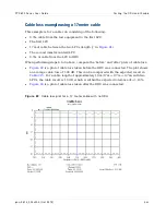
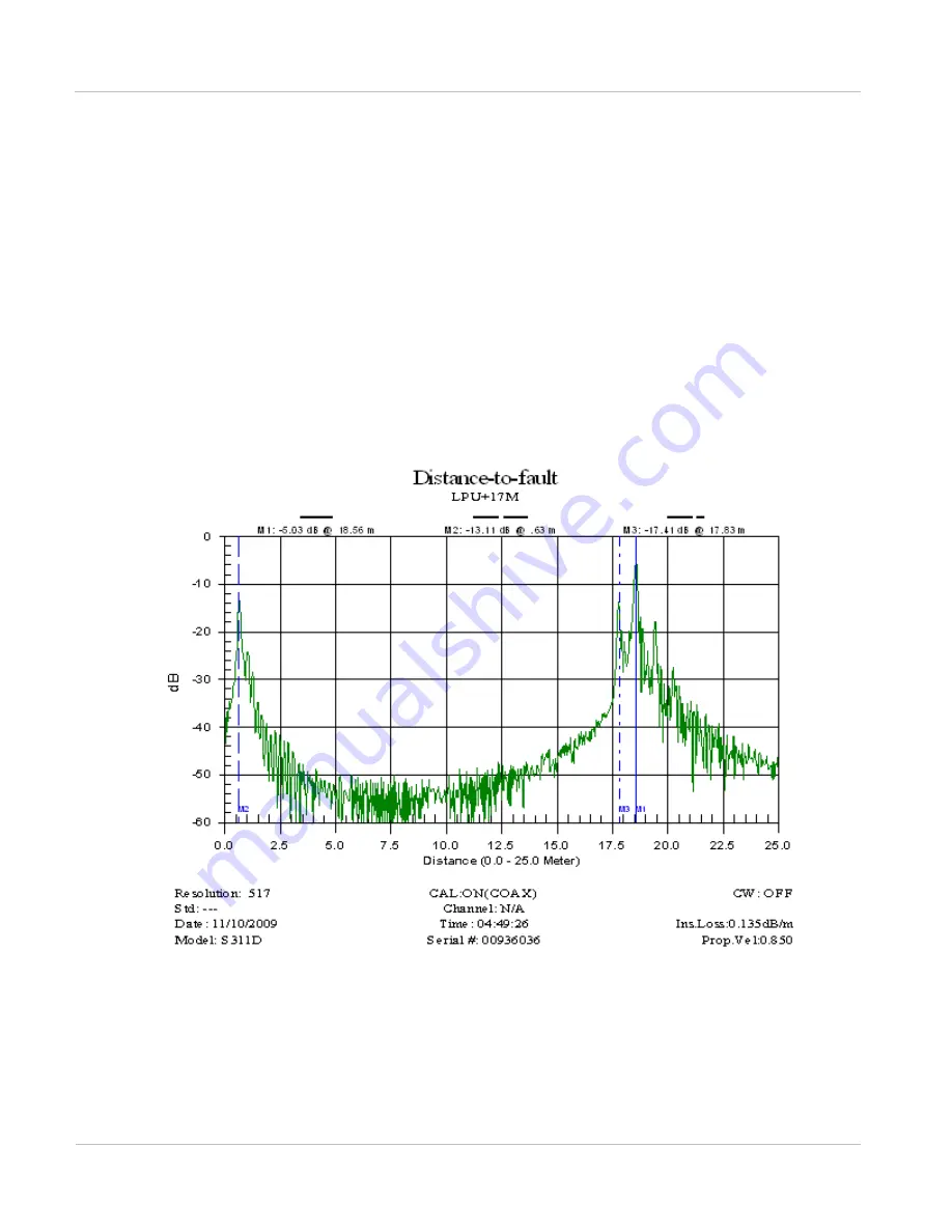
DTF return loss example
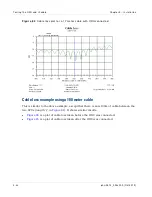
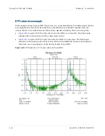
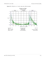
This example shows typical DTF return loss in a good installation. The distances from the
test equipment to first LPU (marker M2), and then the second LPU (marker M3) are
clearly shown. The cable between them shows
no
discontinuity. There are two plots:
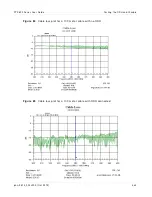
•
is a plot of DTF return loss before the ODU is connected. The final peak
(marker M1) is the position of the cable open circuit.
•
is a plot of DTF return loss after the ODU is connected. The final peak
remains in the same position but is now reduced in amplitude because less signal is
reflected, as a consequence of the better match of the ODU.
Figu r e 8 6
DTF plot for a 17 m et er cable wit h no ODU
Summary of Contents for PTP 800 Series
Page 1: ...Cambium PTP 800 Series User Guide System Release 800 05 02 ...
Page 40: ...Licensing requirements About This User Guide 10 phn 2513_004v000 Oct 2012 ...
Page 232: ...Limit of liability Chapter 3 Legal information 3 22 phn 2513_004v000 Oct 2012 ...
Page 322: ...Radiation hazard assessm ent Chapter 4 Reference information 4 90 phn 2513_004v000 Oct 2012 ...
Page 428: ...Replacing IRFU components Chapter 5 Installation 5 106 phn 2513_004v000 Oct 2012 ...
Page 630: ...Using recovery mode Chapter 7 Operation 7 78 phn 2513_004v000 Oct 2012 ...


