PTP 800 Series User Guide
I nst alling t he CMU
phn- 2513_004v000 ( Oct 2012)
5- 77
Installing the CMU
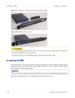
This section describes how to mount the CMU in the building or cabinet, and to connect it
to ground, power supply and PC.
When installing a 1+1 Hot Standby link, install two CMUs at each end, one for the Primary
and one for the Secondary unit.
When installing a 2+0 link, install two CMUs at each end, one for the link ‘A’ and one for
the link ‘B’ ODU.
To minimise radiated emissions, use screened Ethernet cable for all copper connections
from the CMU Ethernet ports. This includes the Data port connection to any network
switch and the Management port to the splitter WB3807 (if fitted) and onwards to any
network switch.
Maximum operating ambient temperature for the CMU
HOT SURFACES: care should be taken when handling an operating CMU.
Mount the CMU on either a horizontal or vertical surface using the supplied mounting
bracket. Do not operate the CMU in ambient temperatures exceeding 40 deg C unless
mounted in a Restricted Access Location.
At ambient temperatures over this limit, the temperature of the external metal case parts
of the CMU may exceed a touch temperature of 70 deg C. Heat warning labels are fixed
adjacent to the hottest parts, on the top of the unit adjacent to the rear face and to
the front panel mounted N type connector.
Operation of CMU in a Restricted Access Location
The CMU may be operated in ambient temperatures up to 55°C when it is housed in a
Restricted Access Location. Under these conditions the temperature of the external metal
case parts of the CMU may exceed a touch temperature of 70°C, but will be less than
90°C.
A Restricted Access Location is defined (in EN 90650-1) as one where access may only be
gained by use of a tool or lock and key, or other means of security, and access is
controlled by the authority responsible for the location.
Summary of Contents for PTP 800 Series
Page 1: ...Cambium PTP 800 Series User Guide System Release 800 05 02 ...
Page 40: ...Licensing requirements About This User Guide 10 phn 2513_004v000 Oct 2012 ...
Page 232: ...Limit of liability Chapter 3 Legal information 3 22 phn 2513_004v000 Oct 2012 ...
Page 322: ...Radiation hazard assessm ent Chapter 4 Reference information 4 90 phn 2513_004v000 Oct 2012 ...
Page 428: ...Replacing IRFU components Chapter 5 Installation 5 106 phn 2513_004v000 Oct 2012 ...
Page 630: ...Using recovery mode Chapter 7 Operation 7 78 phn 2513_004v000 Oct 2012 ...

