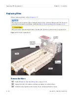
Replacing I RFU com ponent s
Chapt er 5: I nst allat ion
5- 104
phn- 2513_004v000 ( Oct 2012)
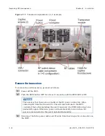
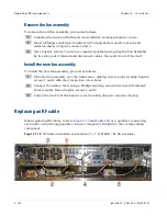
Remove the fan assembly
To remove the old fan assembly, proceed as follows:
1
Unfasten the two front flat-head screws
(#4-40), and keep them for re-use.
2
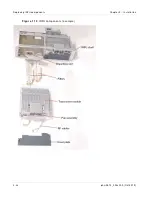
Insert a Phillips small-tip screwdriver in Through-holes A and B to reach and
unfasten the two Captive screws 1 and 2.
3
Once Captive screws 1 and 2 are completely unfastened, grasp the Fan Assembly
by its sides, pull it forward and disconnect cables, then pull it out of the shelf.
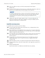
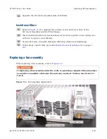
Install the new fan assembly
To install the new fan assembly, proceed as follows:
1
Place the fan assembly over the transceiver, making sure to properly align Captive
screws 1 and 2 with their respective screw holes.
2
Connect the cables; then, using a Phillips small-tip screwdriver inserted through
holes A and B, fasten Captive screws 1 and 2.
3
Fasten the two Front flat-head screws. Carefully observe connector keying
.
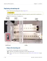
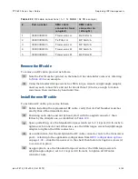
Replacing an RF cable
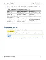
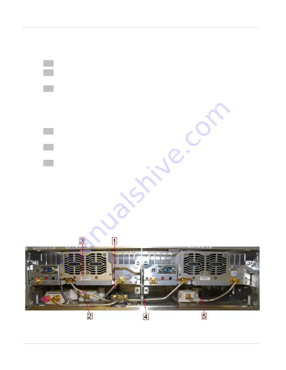
When replacing RF cables, refer to
each cable, using the appropriate connector (angled or straight) to the corresponding
component.
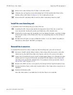
Figu r e 1 1 5
RF cable inst allat ion and rem oval ( 1+ 1 Tx MHSB / Rx SD exam ple)
Summary of Contents for PTP 800 Series
Page 1: ...Cambium PTP 800 Series User Guide System Release 800 05 02 ...
Page 40: ...Licensing requirements About This User Guide 10 phn 2513_004v000 Oct 2012 ...
Page 232: ...Limit of liability Chapter 3 Legal information 3 22 phn 2513_004v000 Oct 2012 ...
Page 322: ...Radiation hazard assessm ent Chapter 4 Reference information 4 90 phn 2513_004v000 Oct 2012 ...
Page 428: ...Replacing IRFU components Chapter 5 Installation 5 106 phn 2513_004v000 Oct 2012 ...
Page 630: ...Using recovery mode Chapter 7 Operation 7 78 phn 2513_004v000 Oct 2012 ...

