Task 6: Configuring prot ect ion
Chapt er 6: Configurat ion and alignm ent
6- 58
phn- 2513_004v000 ( Oct 2012)
If a coupler is used, connect the Primary CMU to the ODU on the MAIN side of the
coupler. This is especially important for an asymmetric coupler where the performance of
the MAIN unit will be enhanced. In this case, set Primary Recovery Period to a non-zero
value to maximize the use of the Main Path.
If antenna protection is used and the two antennas are not the same, connect the Primary
CMU to the more powerful antenna. In this case, for optimum link performance, Primary
Recovery Period must also be set to a non-zero value.
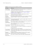
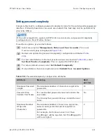
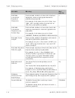
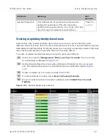
Ta ble 2 3 1
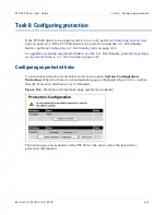
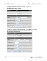
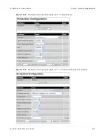
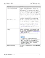
Prot ect ion Configurat ion at t ribut es
At t r ibu t e
M e a n in g
Transmitter
‘Muted’ means that the RFU will not radiate and the
CMU will not forward Ethernet frames between the
wireless interface and the Ethernet ports. This applies
in all conditions.
‘Enabled’ means that the RFU is allowed by the user
to radiate and the CMU is allowed by the user to
forward Ethernet frames between the wireless
interface and the Ethernet ports. However, other
factors may still prevent this, for example if the unit is
the inactive unit at an end of a 1+1 Hot Standby link.
This attribute does not indicate whether the unit
is actually radiating and forwarding Ethernet
Frames, but is a configuration attribute allowing
the unit to radiate and forward traffic if other
factors permit. To see if the unit is actually
radiating and forwarding traffic, examine the
Transmitter Status attribute on the Status page.
Protection
‘Hot Standby 1+1’ means that the link is protected.
‘Hot Standby 1+1 with Rx Diversity’ means that the
link is protected and Receive Diversity is enabled.
'Disabled' means that the link is not protected.
Summary of Contents for PTP 800 Series
Page 1: ...Cambium PTP 800 Series User Guide System Release 800 05 02 ...
Page 40: ...Licensing requirements About This User Guide 10 phn 2513_004v000 Oct 2012 ...
Page 232: ...Limit of liability Chapter 3 Legal information 3 22 phn 2513_004v000 Oct 2012 ...
Page 322: ...Radiation hazard assessm ent Chapter 4 Reference information 4 90 phn 2513_004v000 Oct 2012 ...
Page 428: ...Replacing IRFU components Chapter 5 Installation 5 106 phn 2513_004v000 Oct 2012 ...
Page 630: ...Using recovery mode Chapter 7 Operation 7 78 phn 2513_004v000 Oct 2012 ...

