PTP 800 Series User Guide
Com pact m odem unit ( CMU)
phn- 2513_004v000 ( Oct 2012)
1- 9
CMU interfaces
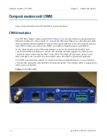
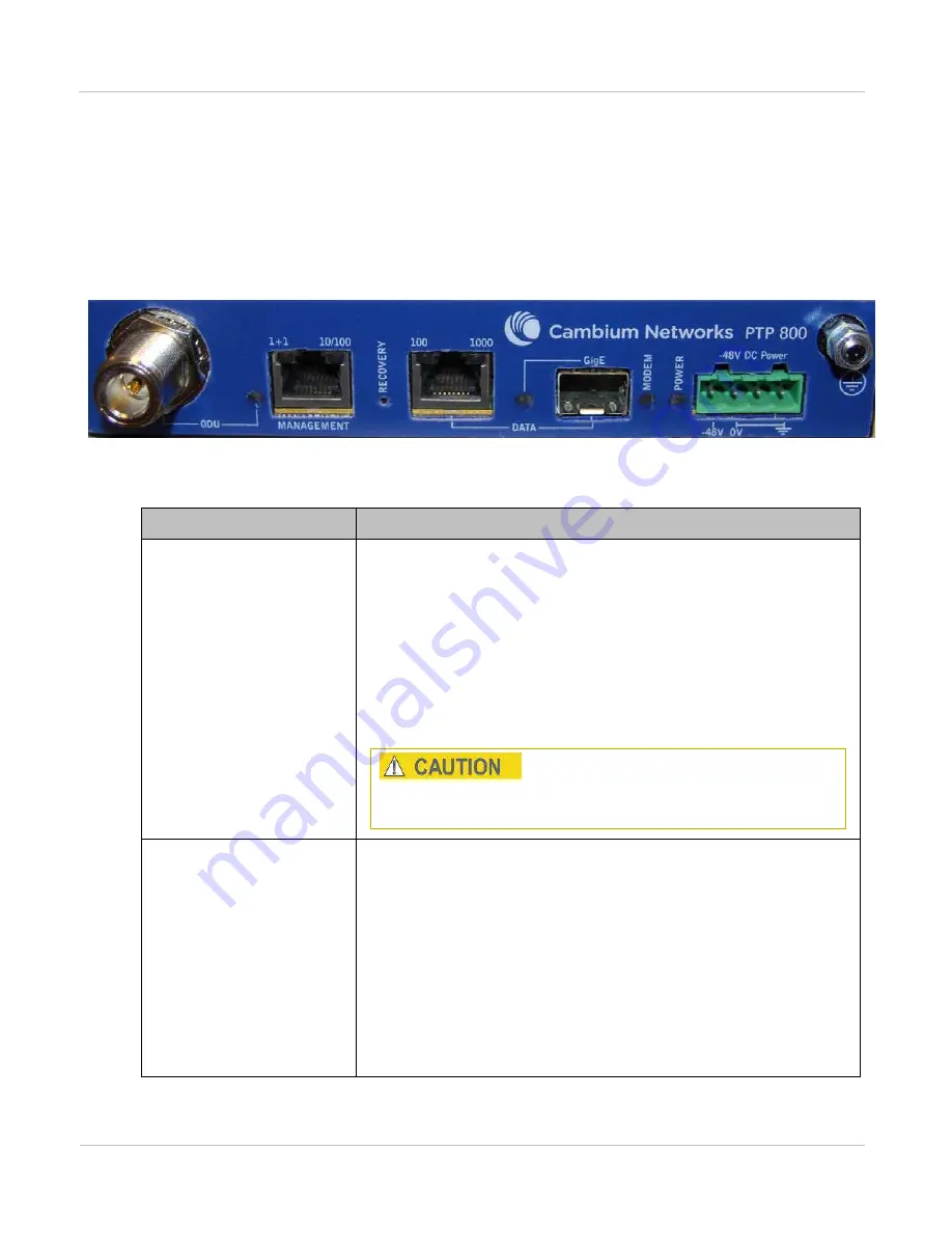
The CMU front panel interfaces are illustrated in
. The
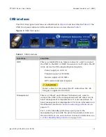
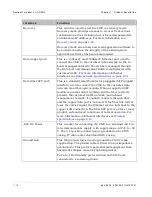
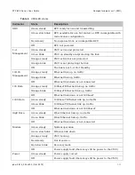
CMU front panel indicator LEDs and their states are described in
Figu r e 4
CMU fr ont panel
Ta ble 4
CMU int erfaces
I n t e r fa ce
Fu n ct ion
ODU
This is a standard N-type female connector, used to connect
the CMU to the ODU or IRFU transceiver via IF cable. The IF
cable carries the following multiplexed signals:
Power supply at –48 V dc
Transmit signal at 350 MHz
Receive signal at 140 MHz
RFU control and status signals
Do not connect or disconnect the IF cable when the –48
V supply is applied to the CMU.
Management
This is a 10baseT and 100baseT Ethernet port, used to
connect the CMU to the management network when ‘out-of-
band’ management is implemented. It is not used when ‘in-
band’ management is implemented. For more information on
the Ethernet interfaces see
on
For 1+1 Hot Standby protection, spare pins in the
management port provide the protection interface between
the two CMUs at one end of a link. For more information see
Summary of Contents for PTP 800 Series
Page 1: ...Cambium PTP 800 Series User Guide System Release 800 05 02 ...
Page 40: ...Licensing requirements About This User Guide 10 phn 2513_004v000 Oct 2012 ...
Page 232: ...Limit of liability Chapter 3 Legal information 3 22 phn 2513_004v000 Oct 2012 ...
Page 322: ...Radiation hazard assessm ent Chapter 4 Reference information 4 90 phn 2513_004v000 Oct 2012 ...
Page 428: ...Replacing IRFU components Chapter 5 Installation 5 106 phn 2513_004v000 Oct 2012 ...
Page 630: ...Using recovery mode Chapter 7 Operation 7 78 phn 2513_004v000 Oct 2012 ...


