PTP 800 Series User Guide
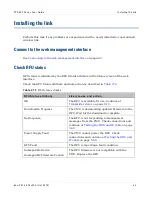
Connect ing t o t he web m anagem ent int erface
phn- 2513_004v000 ( Oct 2012)
8- 5
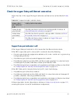
Check the copper Data port Ethernet connection
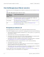
Check the state of the copper Data port indicators and take action as described in
Ta ble 2 6 7
Copper Dat a port indicat or check s
Coppe r D a t a
por t in d ica t or
st a t e
Lik e ly ca u se a n d a ct ion
Yellow steady,
green steady
The Ethernet link is up but is not carrying traffic. Continue at
Yellow blink,
green blink
The Ethernet link is up and is carrying traffic. Continue at
Off
The Ethernet link is down. Continue at
on page
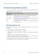
Copper Data port indicator is off
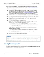
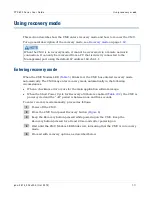
If the Copper Data port indicator is off, it means that the Ethernet link is down.
If the CMU copper data port is connected to a network, check the following:
•
The associated network equipment (workstation, PC, router, switch etc.) is powered up
and operating correctly.
•
The Ethernet port in the associated equipment is enabled.
•
The Ethernet cable between the CMU and the network equipment is connected and is
not damaged. If possible, substitute a known good Ethernet cable.
•
The Ethernet ports have compatible auto negotiation and duplex settings as described
in
Configuring the IP interface and management mode
If the CMU Data port is connected directly to a PC, check the following:
•
The Ethernet port in the PC is enabled.
•
The Ethernet cable between the CMU and the PC is connected and is not damaged. If
possible, substitute a known good Ethernet cable.
•
The Ethernet ports have compatible auto negotiation and duplex settings as described
in
Configuring the IP interface and management mode
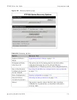
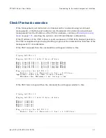
If these steps fail to resolve the problem, continue at
selecting the option to reset IP and Ethernet configuration.
Summary of Contents for PTP 800 Series
Page 1: ...Cambium PTP 800 Series User Guide System Release 800 05 02 ...
Page 40: ...Licensing requirements About This User Guide 10 phn 2513_004v000 Oct 2012 ...
Page 232: ...Limit of liability Chapter 3 Legal information 3 22 phn 2513_004v000 Oct 2012 ...
Page 322: ...Radiation hazard assessm ent Chapter 4 Reference information 4 90 phn 2513_004v000 Oct 2012 ...
Page 428: ...Replacing IRFU components Chapter 5 Installation 5 106 phn 2513_004v000 Oct 2012 ...
Page 630: ...Using recovery mode Chapter 7 Operation 7 78 phn 2513_004v000 Oct 2012 ...


