Page 15 of 16
Configuring the Link
The Web EMS provides wizards to configure radio links. The wizards guide you through configuration of the basic radio
parameters and services necessary to establish a working pipe link.
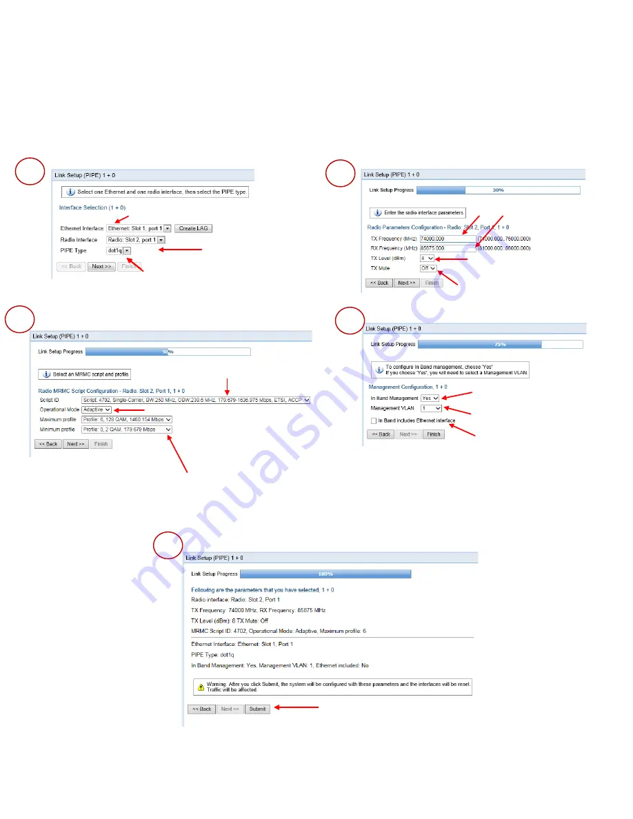
To configure a 1+0 link using the Quick Configuration wizard, select Quick Configuration > PIPE > Single Carrier > 1+0.
Page 1 of the 1+0 Quick Configuration wizard opens.
Set the transmission and
received radio frequency in MHz.
Enter the desired TX signal level
(TSL). The range of values depends
on the frequency and RFU type.
Select
On
or
Off
to mute or
unmute the TX output of the RFU.
Select the MRMC script you want
to assign to the radio.
Select the ACM mode:
Fixed
or
Adaptive
.
If you selected
Fixed
in the
Operational Mode
field, the
Profile
field
appears instead of these fields. Select the ACM profile for the radio in
the
Profile
field.
If you selected
Adaptive
in the
Operational Mode
field, enter the
maximum and minimum profiles for the script in these fields.
•
Fixed ACM mode applies constant TX and
RX rates.
•
In Adaptive ACM mode, TX and RX rates are
dynamic. An ACM-enabled radio system
automatically chooses which profile to use
according to channel fading conditions.
Select
Yes
to configure in-band
management or
No
if you do not
need in-band management.
If you selected
Yes
above, select
the management VLAN.
Select this box if you want to use the
Ethernet interface as well as the radio
interface for in-band management.
Review the parameters and click
Submit
to
complete configuration of the link. After you
click
Submit
, the unit is reset.
2
3
4
5
Select the Attached Interface type for
the service that will connect the radio
and Ethernet interfaces:
Select a radio
interface for the link.
Select an Ethernet interface or LAG for the link.
Click
Create LAG
to open a wizard that guides
you through the steps to create a LAG.
•
s-tag
– All S-VLANs and untagged
frames are classified into the service.
•
dot1q
– All C-VLANs and untagged
frames are classified into the service.
1
Summary of Contents for PTP 820E
Page 1: ...Quick Installation Instructions PTP 820E System Release 10 9 ...
Page 4: ...Page 4 of 16 PoE Injector PoE Injector Interfaces ...
Page 7: ...Page 7 of 16 Cabling To connect an optical Ethernet cable and SFP ...
Page 8: ...Page 8 of 16 To connect an electrical Ethernet cable To connect a DC power cable ...


