Page 61 of 99
Installation Procedure and Antenna
Alignment – 1+0 with 43 dBi Flat Antenna
and Alignment Device
When you order an PTP 850E with a 43 dBi flat antenna, the radio and antenna are delivered
together as a single unit. The polarization is determined by the placement of the radio-
antenna unit.
Figure 12 Installation and Alignment Device – Azimuth and Elevation Adjustment
Tools
The installation and alignment device enables you to easily adjust the antenna’s azimuth
and elevation, in gross and fine intervals. Gross alignment enables you to adjust the azimuth
and elevation in 15° increments. Fine alignment enables you to make more precise
adjustments by turning the Azimuth and Elevation nuts such that each ¼ turn is equal to an
adjustment of 0.25°.
There are two M8 Elevation Screws and two M8 Azimuth screws, as shown in
Figure 12
.
Before starting the alignment, make sure these screws are securely in place so they will not
fall out during the procedure, but not too tight, so as to enable you to manually adjust the
azimuth and elevation to the approximate position you want, before performing exact
antenna alignment as described in the following sections.
Summary of Contents for PTP 850E
Page 1: ...Installation Guide PTP 850E System Release 10 9 ...
Page 41: ...Page 41 of 99 1 Secure the cable to the gland using a tie wrap ...
Page 50: ...Page 50 of 99 4 Tighten the gland cap 5 Secure the cable to the gland using a tie wrap ...
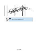
Page 60: ...Page 60 of 99 Note For this type of installation a 2RU space is required ...
Page 70: ...Page 70 of 99 2 Manually adjust the azimuth base to its required location ...
Page 73: ...Page 73 of 99 2 Move the Elevation Adaptor to the required location ...

