Cambridge Air Solutions
36
S-Series Technical Manual
INSTALLATION INSTRUCTIONS
VERTICAL S-SERIES STRUCTURAL FILTER SECTION
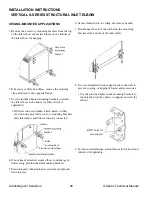
CEILING-MOUNTED APPLICATIONS
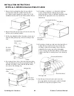
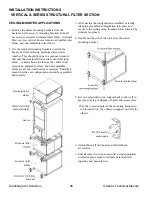
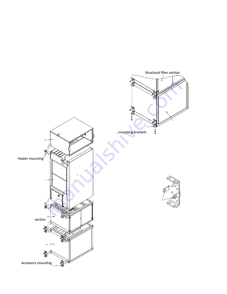
1. Remove the heater mounting brackets from the
heater and all accessory mounting brackets from all
necessary accessories (structural inlet elbow, structural
filter sec-tion, vertical duct extensions, adjustable inlet
elbow, and non-adjustable inlet elbow).
2. Use the removed mounting brackets to attach the
heat-er and all previously mentioned accessories
together. This should be done in a manner to ensure
that only the structural filter section, structural inlet
elbow , or heater bears the load as the vertical duct
extensions, adjustable elbow, and non-adjustable
elbow are all non-load bearing accessories. This likely
means that the unit configuration should be assembled
horizontally.
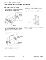
3. After having the configuration assembled, carefully
lift entire assembled configuration into place and
secure to the ceiling using threaded rod as directed by
structural engineers.
4. Double nut the end of the rod below the lowest
mounting bracket.
5. It is recommended to run support back to the wall to
prevent swaying or tipping of heater and accessories.
• Use the provided holes in the mounting brackets to
run threaded rod (by others) to support on walls (by
others).
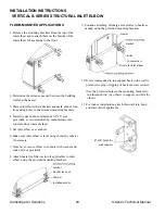
6. Attach thru-wall rain hood and all additional
accessories.
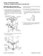
7. Seal all seams between accessories using appropriate
contractor grade caulk to mitigate potential water
ingestion and pressure loss.
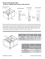
Non-adjustable
elbow
brackets (Qty 8)
brackets
Structural inlet
elbow
Structural filter
Heater
Accessory
Structural inlet elbow
Ø 5/8” holes for
wall support
Non-adjustable
elbow
brackets (Qty 8)
brackets
Structural inlet
elbow
Structural filter
Heater
Accessory
Structural inlet elbow
Ø 5/8” holes for
wall support
Non-adjustable
elbow
brackets (Qty 8)
brackets
Structural inlet
elbow
Structural filter
Heater
Accessory
Structural inlet elbow
Ø 5/8” holes for
wall support

