S-Series Technical Manual
53
Cambridge Air Solutions
THERMISTOR SENSOR
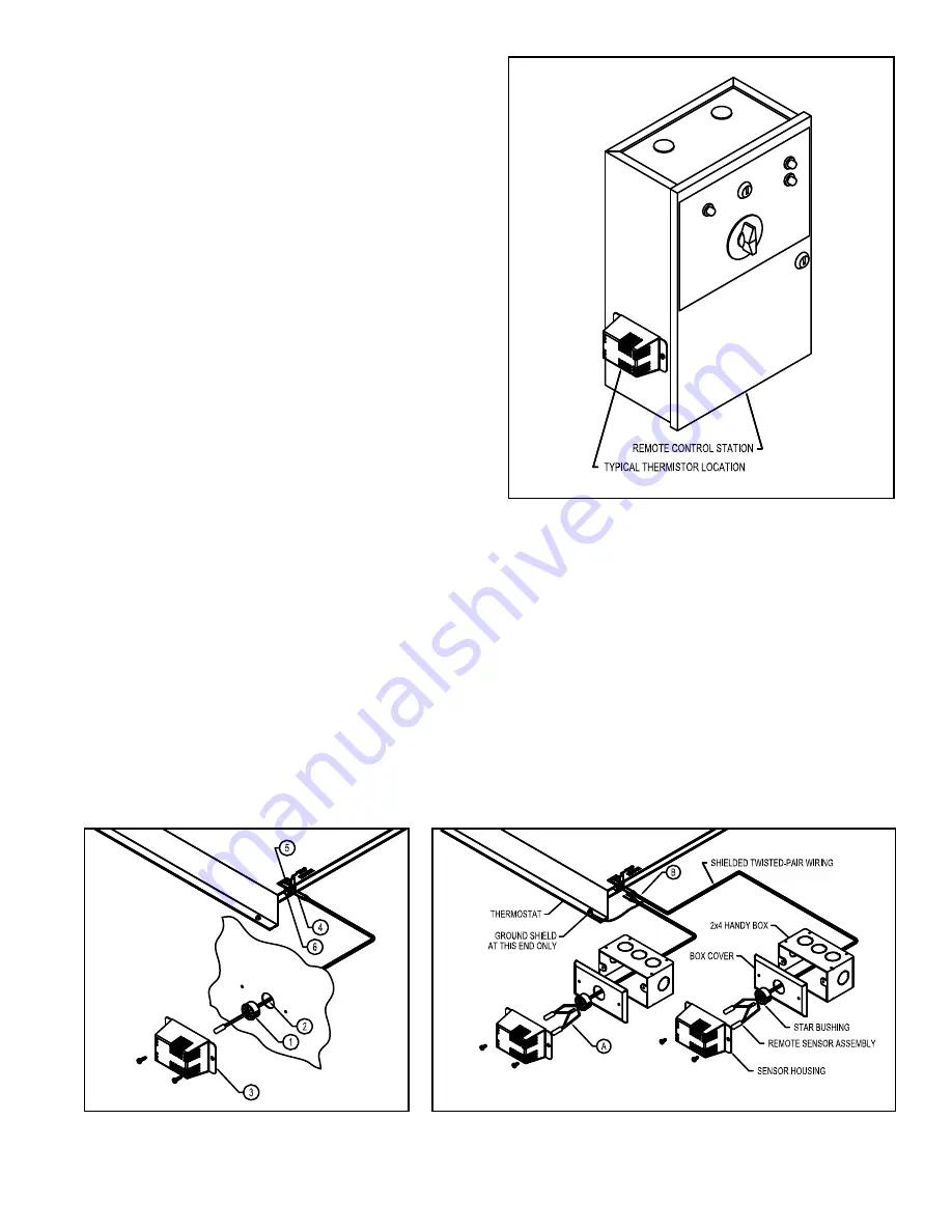
The thermistor enclosure is packed inside the Remote Control
Station for shipment. It can be mounted on the exterior sides
or bottom of the Remote Control Station (see Figure 1). It
can also be mounted in a remote loca-tion within 500 feet of
the Remote Control Station using 18 gauge stranded, twisted-
pair, shielded cable. The thermistor is wired to the TEMP.
SENSOR terminal block on the thermostat.
THERMISTOR INSTALLATION
(See Figure 2)
1. Insert the star bushing through the opening in
the enclosure.
2. Run the thermistor leads through the star bush-
ing.
3. Attach the cover to the enclosure over the therm-
istor sensor.
4. Separate and strip the ends of the lead wires
3/8".
5. Open the terminal blocks for the sensor connec-
tions.
6. Insert the lead wires and close the terminal
blocks to the locked position.
NOTE: For remote sensors connected with shielded
cable, ground the shield at the thermostat end only.
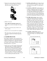
Figure 1
TEMPERATURE AVERAGING (TAS-2) OPTION
(See Figure 3)
The TAS-2 option allows one thermostat to have two
sensing locations. Each enclosure has two thermistor
sensors prewired in series (see A). The sensor leads
are then connected to the thermostat in parallel (see B).
The thermostat display will show the average of the
tempera-tures at the two sensing locations. The TAS-2
is a unique application. Consult the design drawing and/
or your Cambridge Representative for placement assis-
tance.

