Cambridge Air Solutions
60
S-Series Technical Manual
b. Insert key and turn the mode selector switch to the
“HEATING” position.
c. Set the operating thermostat, if applicable, to its
highest setting or activate that part of the control
system which will initiate blower and burner
operation
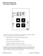
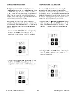
For Remote Control Station - Security (RCS-S),
refer to the Operating Instructions for the Operating
Electronic Thermostat (OET) (page 64).
For Temperature Setback System (TSS), refer to the
Operating and Programming Instructions for the
TSS Controller (page 66).
If another interlock device controls the operation of
the heater, activate this device.
d. After the motorized discharge damper opens, the
blower motor will start.
e. After a delay for prepurge and igniter warmup, the
burner will ignite.
f. Adjust the temperature control system and verify the
heater output changes correspondingly.
For EDSM, adjust the Space Temperature Selector.
For EDR, adjust the Remote Heat Adjust.
g. Reset the operating thermostat, if applicable, and
the temperature control system, if applicable, to the
desired temperature. If the Entering Air Thermostat
was adjusted, reset to its previous setting.
h. Turn the mode selector switch to the “SUMMER
VENTILATION” position. Verify the blower oper-
ates. In TSS applications, the override timer may
need to be activated to initiate operation.
i. Turn the mode selector switch to the desired
operating mode.
CALIBRATION PROCEDURES
EDL CONTROL SYSTEMS
(MAXITROL SERIES 14)
1. Turn the blower and burner service switches to the
“OFF” position.
2. Turn the heater disconnect switch to the “ON”
position.
3. Adjust the temperature setting on the amplifier dial
to 160°.
4. Turn the blower service switch to the “LOCAL”
position. The blower motor will start.
5. Turn the burner service switch to the “LOCAL”
position. After a delay for prepurge and igniter
warm-up, the burner will light. Allow 5 minutes for
the sampling box temperature to stabilize.
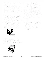
6. Adjust the calibration potentiometer as shown in
the drawing. To raise the discharge temperature
adjust the dial clockwise. To lower the discharge
temperature adjust the dial counterclockwise.
7. Wait for the discharge temperature and manifold
pressure to stabilize. Do not rush this step.
8. Repeat steps 6 and 7 until the mixing box
temperature has stabilized at 155°-160°.
9. Remove the thermocouple from the Sampling Box
port and replace the Sampling Box cover. Close the
heater access doors.
10. Verify that the discharge temperature and
manifold pressure comply with the guidelines of
the Calibration Check procedure step 8b. Repeat
steps 1 through 9 if necessary.
11. Turn the disconnect switch to the “OFF” position.
12. Turn the blower and burner service switches to the
“REMOTE” position.

