Cambridge Air Solutions
76
S-Series Technical Manual
NETWORK CONNECTION
•
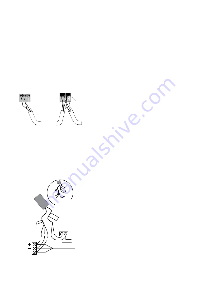
Use stranded 3-wire twisted pair, shielded
cable to connect to FC BUS (blue) terminals.
•
Run all low-voltage wiring and cables
separate from high-voltage wiring.
•
Connect the – terminals in parallel with
all other – terminals and the + terminals in
parallel with all other + terminals.
•
The FC bus Shield (SHD) terminal is
isolated and can be used to as a shield drain
connection.
Stranded 3-Wire Twisted Shielded Cable
Isolated Shield
Connection
Terminal
+
_
C
O
M
SH
D
To Next
Device on
the FC Bus
Segment
FC Bus
Terminal
Block Plugs
+
_
C
O
M
SH
D
Terminating Device
on FC Bus Segment
To Next
Device on
the FC Bus
Segment
Daisy Chained Device
on FC Bus Segment
END-OF-LINE TERMINATION
If a controller is on either end of a BACnet MS/TP
network an EOL terminator (JCI # MS-BACEOL-0)
must be installed for proper network operation.
FC B
us
Clas
s 2
AC
24 V
~
REF
24
V~H
ot
24
V~C
om
FC or Bus Cable from
Previous Device on
Daisy-Chained Bus Segment
To 24 VAC
Class 2
Power Supply
BLK
BLK
EOL
Terminator
Class
2
AC
24 V
~
FC or N2 Bus
Terminals
Supply
Power
Terminals
BLU
WHT
WHT
FI
G
_E
O
LT
_W
R
N
G
BLK +
BLU
REF
WHT-
Isolate and insulate the REF
lead when connecting the
EOL to third-party devices
with only + and - terminals.
24V~
FC B
us
NETWORK PARAMETERS
Before operating controllers on a bus, you must set
a valid and unique device address for each controller
on the bus through the local display or MAP gateway.
Device addresses 4 through 127 are the valid addresses
for these controllers. The MAC address is set for a
default of 4.
The baud rate is set for a default of Auto. The controller
will listen for the bus supervisor to communicate
first; then automatically set its baud rate to the bus
supervisor’s baud rate. If you anticipate critical peer-
to-peer communication and therefore do not want the
controllers to wait for the bus supervisor to establish the
baud rate, you can specify the baud rate for each device
immediately at startup.
To change any of the network settings (Device
Name, Description, Address, Device Object ID) go to
Controller > Network from the local display or MAP
gateway.
NOTE: When changing any network parameters it is
recommended that the controller be disconnected from
the network while the changes are being made and that
the power be cycled to the controller after all changes
have been made before reconnecting the controller to
the network.

