background image

Cambridge Air Solutions 

84 

S-Series Technical Manual

Problem

Possible Cause

Corrective Action

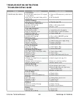
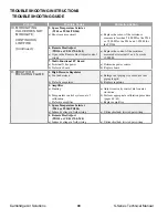
II.   BLOWER RUNS;  


NO HEAT;  


FLAME SAFETY 

RELAY DOESN’T 

LOCK OUT

1. Mode Selector Switch

a) Switch in VENT position

b) Defective Switch

a) Place switch in HEAT position.

b) Replace switch.

2. Burner Service Switch

a) Switch in OFF position

b) Defective switch

a) Place switch in REMOTE position.

b) Replace switch.

3. Multi-Functional PC Board

a) No input voltage on Terminal W (RCS)

b) Inlet temperature above EAT setpoint

c) Improper wiring

d) Defective board

a)  Check voltage in RCS.

b)  Adjust EAT setpoint.

c)   Check  wiring.

d)  Replace multi-functional PC board.

4. Airflow Switch

a) Blower running backwards

b) Belts slipping

c) Blocked intake or discharge

d) Clogged airflow tubing or pickup ports

e) Defective switch

a)  Reverse motor direction.

b)  Tighten and/or replace belts.

c)  Find and remove obstruction.

d)   Clean or replace tubing or pickup ports.

e)  Replace switch.

5. Flame Safeguard Relay

a) No input voltage

b) Defective FSR

a)  Check wiring.

b)  Replace FSR.

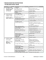
III.   BLOWER RUNS; 


NO HEAT; 


FLAME SAFETY 

RELAY LOCKS OUT

1. Igniter

a) No current (open igniter)

b) No voltage

During trial for ignition:

a)  Check igniter current.

b)  Check FSR output to igniter. 

2. High Limit

a) High limit tripped

a) See Problem Number VI (page 86).

3. High or Low Gas Pressure Switches

a) Low gas pressure switch tripped

b) High gas pressure switch tripped

c) Defective gas pressure switch

a)    Check gas supply for low gas pressure or 

no gas.

b1)  Check manifold gas pressure for high 

pressure reading and reset pressure 

regulator.

b2)  Check gas supply pressure against name 

plate.

b3)  Verify the high pressure regulator is a 

lock-up type.

c)  Replace gas pressure switch.

4. Gas Valve

a) No input voltage

b) Gas valve does not open

c) Defective solenoid

a1)  Check FSR output to R1 relay 

during ignition trial.

a2) Check gas valve circuit and wiring.

b1)  Compare supply voltage to nameplate 

voltage.

b2) Clean and/or replace gas valve parts.

c)  Replace solenoid or valve assembly.

5. Modulating Valve

a) Minimum fire set too low

a) Adjust minimum fire on modulating valve. 

6. Multi-Functional PC Board

a) Low fire start set too low

b) Thermistor open or not connected

a)  Adjust modulating valve voltage between 

10 and 13 Volts DC.

b) Properly install or replace thermistor.

TROUBLESHOOTING INSTRUCTIONS

  TROUBLESHOOTING GUIDE

Summary of Contents for S Series

Page 1: ...ance instructions thoroughly before installing or servicing this equipment FOR YOUR SAFETY The use and storage of gasoline or other flammable vapors and liquids in open containers in the vicinity of this appliance is hazardous FOR YOUR SAFETY If you smell gas 1 Open windows 2 Don t touch electrical switches 3 Extinguish any open flame 4 Immediately call your gas supplier 90 1 ASHRAE ASHRAE COMPLIA...

Page 2: ...estions regarding Limited Warranty contact Cambridge Air Solutions Customer Service Group at 1 800 473 4569 S SERIES BLOW THRU SPACE HEATER TECHNICAL MANUAL Copyright 2020 Cambridge Air Solutions All Rights Reserved Cambridge Air Solutions 760 Long Road Crossing Dr Chesterfield MO 63005 Phone 636 532 2233 800 899 1989 Fax 636 530 6133 www cambridgeair com ...

Page 3: ...ion 34 S Series 24 38 50 Wall Sleeves 37 S Series Downturn With Lugs 39 S Series Upturn 41 Horizontal S Series 4 Mounting Stand 43 Vertical Inlet Skirt 46 Rain Hood Inlet Skirt 47 Unit Inlet Skirt 48 Gas Piping 49 Electrical Wiring 50 Remote Control Station and Temperature Sensor Locations 51 Thermistor Sensor 53 Start Up Instructions 54 Calibration Procedures 60 Operating Instructions 63 Operatin...

Page 4: ... structure s designed infiltration rate by providing properly sized relief openings or by interlocking a powered exhaust system or by a combination of these methods If the failure or malfunction of this heater creates a hazard to other fuel burning equipment in the building e g when the heater is providing the make up air to a boiler room the unit is to be interlocked to open inlet air dampers or ...

Page 5: ...harge Duct DE Directional Elbows DT Downturn FS Filter Section ID Inlet Duct IE Inlet Elbow IP Inlet Plenum ISR Inlet Skirt Rain Hood ISU Inlet Skirt Unit MC Mounting Curb MDD Motorized Discharge Damper MR Mounting Rail RH RT Rain Hood Roof Top RH TW Rain Hood Thru Wall Component Identification RH RT MDD UNIT MR AMS DE DT WALL SLEEVE BY OTHERS Roof Top Thru Wall Mounting Under Roof Mounting IE UNI...

Page 6: ...TAL MOUNTING STAND FILTER SECTION SUPPORT DUCT EXTENSION DUCT EXTENSION ADJUSTABLE ELBOW WALL SLEEVE DIRECTIONAL ELBOWS DOWNTURN DOWNTURN DOWNTURN DIRECTIONAL ELBOWS STRUCTURAL INLET ELBOW RAINHOOD RAINHOOD EXTENSION ADJUSTABLE STAND DUCT EXTENSION STRUCTURAL FILTER SECTION DOWNTURN DOWNTURN DIRECTIONAL ELBOWS ADJUSTABLE STAND WALL SLEEVE ...

Page 7: ...mbridge S Series Blow Thru heaters are utilized to meet the space heating requirements of commercial or industrial buildings The control system is typically designed to cycle the heaters on and off in response to the rise and fall of the space temperature The heater will discharge air at the temperature selected up to 160ºF The operating thermostat is typically located near the perimeter of the bu...

Page 8: ...restricted in any way that would affect the rated airflow through the heater or affect the desired air distribution pattern of the heater It is the responsibility of the installer to communicate any potential problems with the installation to the person or persons responsible for providing the installation instructions or drawings prior to proceeding with the installation IMPORTANT Where the mount...

Page 9: ...S800 65 33 25 3 8 S950 S1200 S1600 78 5 8 33 42 S1850 S2200 S3200 90 36 47 1 8 STAND DETAIL NOTES 1 TREATED TIMBER AS REQUIRED UNDER MOUNTING CURB RAIL AND STAND TO SECURE AND LEVEL UNIT 2 SECURE MOUNTING STAND TO TIMBER WITH WOOD LAG SCREWS AS SHOWN 3 SECOND MOUNTING ASSEMBLY IS REQUIRED ONLY ON UNITS WITH FILTER SECTIONS 4 MOUNTING STAND CONSTRUCTION 12 GA GALVANIZED STEEL 5 MOUNTING RAIL CONSTR...

Page 10: ...ND DETAIL NOTES 1 TREATED TIMBER AS REQUIRED UNDER MOUNTING RAIL AND STAND TO SECURE AND LEVEL UNIT 2 SECURE MOUNTING STAND TO TIMBER WITH WOOD LAG SCREWS AS SHOWN 3 THIRD MOUNTING ASSEMBLY IS REQUIRED ONLY ON UNITS WITH FILTER SECTIONS 4 MOUNTING STAND CONSTRUCTION 12 GA GALVANIZED STEEL 5 MOUNTING RAIL CONSTRUCTION 18 GA GALVANIZED STEEL 6 REMOVE HANGER BRACKET AND REPLACE SCREWS 7 STAND IS ADJU...

Page 11: ...d mounting rail s should be installed so that the heater will mount level Cambridge recommends mounting the heater a minimum of 24 off the roof surface in areas where snow accumulation could impact heater operations 3 Attach the mounting stands to the heater while the heater is on the ground Adjust the height of the stands so the heater inlet is slightly 1 8 below level lower than the discharge Th...

Page 12: ... ENCLOSURE PROVIDED WITH EXTERNAL GAS TRAIN MOUNTING RAIL FILTER SECTION UNIT DOWNTURN OPTIONAL COUNTERFLASHING MOUNTING CURB DISCHARGE DUCT DIRECTIONAL ELBOWS TYPICAL INSTALLATION ROOF TOP MOUNTING 10 12 2 X 4 TREATED LUMBER PROVIDED 2 X 6 TREATED LUMBER BY OTHERS TREATED LUMBER BY OTHERS ROOF TREATED LUMBER BY OTHERS OPENING 24 TREATED LUMBER THICKNESS OF ROOF INSULATION AS REQUIRED UNDER MOUNTI...

Page 13: ...eater On S400 S800 model heaters rotate the mounting brackets 180 and retighten the securing hardware 5 Use a forklift or comparable lifting device to raise and position the heater Take precautions to prevent equipment damage dents and or scratches when the heater is being lifted into position 6 Use washers and double lock nuts to secure the unit on the hanging rods IMPORTANT The discharge end of ...

Page 14: ...ALVE HIGH PRESSURE SUPPLY TAP LOW PRESSURE SHUT OFF VALVE OPTIONAL BY OTHERS CONTROL WIRING CONDUIT BY OTHERS VENT PIPE TO OUTDOORS LOCATE MIN 10 FT FROM INTAKE VENT w SCREEN INCOMING POWER BY OTHERS EXTERIOR WALL TRIM INLET GAS PIPE BY OTHERS OPTIONAL FILTER SECTION HANGING ROD DETAIL HANGING BRACKET DETAIL HANGING ROD WASHER WASHER NUT DOUBLE LOCK NUTS DOUBLE LOCK NUTS SHIPPING POSITION NUT WASH...

Page 15: ...eas where snow accumulation could impact heater operations 3 Attach the mounting stands to the heater while the heater is on the ground Adjust the height of the stands so the heater inlet is slightly 1 8 below level lower than the discharge This allows any ingested moisture to drain out of the heater through weep holes located at the inlet of the heat er onto the roof surface 4 Use a crane or comp...

Page 16: ...PTIONS ELECTRICAL CONTROL ENCLOSURE PROVIDED WITH EXTERNAL GAS TRAIN MOUNTING RAIL FILTER SECTION UNIT DOWNTURN OPTIONAL ELBOWS DIRECTIONAL INTERIOR WALL TRIM BY OTHERS WALL SLEEVE BY OTHERS EXTERIOR WALL TRIM TYPICAL INSTALLATION ROOF TOP THRU WALL MOUNTING 10 12 2 X 4 TREATED LUMBER PROVIDED 2 X 6 TREATED LUMBER BY OTHERS TREATED LUMBER BY OTHERS Dimensions allow for 1 clearance on each side ...

Page 17: ...ting structure should be installed such that the heater s inlet plenum will mount level 3 Seal all roof penetrations to prevent roof leaks 4 Lower the inlet duct through the mounting curb and the roof opening 5 Secure the inlet plenum to the curb 6 Connect inlet accessories to the heater including filter section optional and inlet elbow prior to lifting the heater in place 7 Install hanging rods t...

Page 18: ...CURB TO SECURE AND LEVEL THE UNIT AND TO SPREAD THE LOAD BY OTHERS TYPICAL INSTALLATION UNDER ROOF MOUNTING HANGING ROD DETAIL HANGING BRACKET DETAIL HANGING ROD WASHER WASHER NUT DOUBLE LOCK NUTS DOUBLE LOCK NUTS SHIPPING POSITION NUT WASHER WASHER HANGING ROD L BRACKET FOR S400 S800 UNITS C BRACKET FOR S950 S3200 UNITS HANGING RODS NUTS AND WASHERS BY OTHERS ...

Page 19: ...e the lag bolts used to fasten the unit to the skid Rotate the hanging brackets for the vertical application and retighten the securing hardware 5 Utilizing the lifting brackets on the front of the heater use a forklift or comparable lifting device to raise and position the heater Take precautions to prevent equipment damage dents and or scratches when the heater is being lifted into position 6 Us...

Page 20: ...ER mWARNING The primary structural support element of a vertically mounted heater is the base Any support to the heater cabinet should be considered secondary only as a means to help stabilize the heater HANGING BRACKET DETAIL L BRACKET FOR S400 S800 UNITS C BRACKET FOR S950 S3200 UNITS HANGING RODS NUTS AND WASHERS BY OTHERS HANGING ROD DETAIL DOWNTURN SECOND DOWNTURN OPTIONAL MOUNTING POSITION S...

Page 21: ...t to the skid 5 Utilizing the lifting brackets on the front of the heater use a forklift or comparable lifting device to raise and position the heater Take precau tions to prevent equipment damage dents and or scratches when the heater is being lifted into posi tion 6 Secure the heater in place with contractor supplied hardware 7 Install the wall sleeve to the downturn 8 Install fiberglass insulat...

Page 22: ...CTION CHANNEL SUPPORT BY OTHERS SECURE STRUCTURAL CHANNEL TO WALL AS REQUIRED BUILDING WALL BUILDING FOOTING BY OTHERS OPTIONAL FIELD CONNECTED GAS TRAIN WIRING ELBOWS DIRECTIONAL BASE OF HEATER GAS TRAIN BY OTHERS INTERIOR WALL FLASHING MOUNTING DETAIL DOWNTURN mWARNING The primary structural support element of a vertically mounted heater is the base Any support to the heater cabinet should be co...

Page 23: ...nted applications when hanging the unit with threaded rod The elbow is insulated to prevent condensation and reduce noise levels brackets 4 plcs Airflow Stand Mounted Structural inlet elbow Floor Mounted Structural inlet elbow Ceiling Mounted Structural inlet elbow A B C Retaining clip Retaining clip downblast brackets 4 plcs Airflow Stand Mounted Structural inlet elbow Floor Mounted Structural inle...

Page 24: ...ng brackets 5 Position heater with attached accessories upright and lift into place 6 Secure threaded rod to ceiling structure as needed 7 Double nut the end of the rod below the mounting bracket at the bottom of the inlet elbow 8 It is recommended to run support back to the wall to prevent swaying or tipping of heater and accessories Use the provided holes in the mounting brackets to run threaded...

Page 25: ...eeded 5 It is recommended to run support back to the wall to prevent swaying or tipping of heater and accessories Use the provided holes in the mounting brackets to run threaded rod by others to support on walls by others 6 For indoor installations attach thru wall rain hood and inlet skirt if applicable Ø 5 8 holes for wall support Heater bracket Bolts Lock washers Structural inlet elbow Structur...

Page 26: ...plicable to inlet elbow using the provided mounting brackets 9 Continue attaching discharge accessories to heater as needed using the provided mounting brackets 10 It is recommended to run support back to the wall to prevent swaying or tipping of heater and accessories Use the provided holes in the mounting brackets to run threaded rod by others to support on walls by others 11 For indoor installa...

Page 27: ...ured horizontal to the wall in stand mounted applications The discharge end of the elbow attaches easily to wall sleeves or downturns with lugs directional elbows with a discharge collar can also be attached directly to the non adjustable elbow if desired Non adjustable elbows are insulated to help mitigate noise and thermal losses Model Weight A B C S400 S800 45 lbs 13 25 3 8 25 3 8 S950 S1200 S1...

Page 28: ...ollar to the discharge face of the non adjustable elbow and secure using self tapping screws Arrange the directional elbows in the desired configu ration before securing them to the discharge collar 6 Seal all seams between heater and accessories using appropriate contractor grade caulk to mitigate potential water ingestion and pressure loss Non adjustable elbow Accessory bracket Heater Non adjust...

Page 29: ... Item Description Qty 1 Adjustable stand assembled 1 2 Template 1 3 Leveling shims 20 Stand Size Weight Heater Stand Footprint Anchor Locations o Sonotube Locations A B C D E F S400 S800 176 lbs 25 1 2 25 1 2 16 3 4 16 3 4 19 7 8 19 7 8 S950 S1200 S1600 196 lbs 28 42 19 1 2 33 1 2 36 1 2 22 1 2 S1850 S2200 S3200 222 lbs 37 1 2 47 28 7 8 38 1 2 41 5 8 32 1 Determine distance needed between building...

Page 30: ...f shimming necessary insert provided shims where needed to level the stand Once level and square secure base to anchors with washer and lock nut not provided Shims are NOT intended to be used for ad justing the overall stand height See next step 8 Determine if default stand height 48 is correct for heater installation If adjustment needed remove height adjust ment bolts 2 leg and raise stand neces...

Page 31: ... of inlet accessory using includ ed mounting brackets and hardware 10 If provided assemble angled inlet skirt pieces and attach to stand using self drilling screws not provided Attach close off panel to stand and skirt on side nearest wall using self drilling screws not provided 3 8 Bolts and lock washers Heater bracket 4 plcs Heater Inlet skirt Skirt close off panel Self drilling screws Structural...

Page 32: ...ring the duct work to the building structure All ducts are insulated with 1 fiberglass insulation to mitigate thermal losses and reduce vibrations and noise Heater Size Duct Weight A B C S400 S800 3 95 lbs 36 25 3 8 25 1 4 4 135 lbs 48 25 3 8 25 1 4 5 160 lbs 60 25 3 8 25 1 4 S950 S1200 S1600 3 120 lbs 36 28 1 8 42 4 165 lbs 48 28 1 8 42 5 200 lbs 60 28 1 8 42 S1850 S2200 S3200 3 140 lbs 36 37 1 2...

Page 33: ... holes in the mounting brackets to run threaded rod by others to support on walls by others Duct extension or upturn Bolts Lock washers Heater Duct extension bracket bracket Bolts Lock washers Duct extension Duct extension or upturn bracket bracket Ø 5 8 holes for wall support Duct extension or upturn Bolts Lock washers Heater Duct extension bracket bracket Bolts Lock washers Duct extension Duct e...

Page 34: ...attach easily to wall sleeves where the height adjustability allows for an easier alignment of the wall sleeve with the wall hole Downturns with lugs or directional elbows with a discharge collar can also be attached directly to the adjustable elbow if needed in indoor applications This accessory cannot directly attach to an unit due to its in terference with the heater s gas train Adjustable elbo...

Page 35: ...retaining clip and side attachment plates Follow additional installation steps detailed in the appropriate accessory installation instructions 4b If attaching a discharge collar and directional elbows replace the removed screws that were securing the side attachment plates Attach the discharge collar to the discharge face of the adjustable elbow and secure using self tapping screws Arrange the dir...

Page 36: ...om the ceiling or mounted on top of the 4 adjustable mounting stand or structural inlet elbow with 4 accessory mounting brackets It is capable of using permanent disposable or MERV 13 filters All Structural Filter Sections are insulated and double skinned to help mitigate con densation noise and thermal losses Model Weight A B C S400 S800 150 lbs 30 3 8 25 3 8 25 3 8 S950 S1200 S1600 175 lbs 25 3 ...

Page 37: ... instructions 4 It is recommended to run support back to the wall to prevent swaying or tipping of heater and accessories Use the provided holes in the mounting brackets to run threaded rod by others to support on walls by others 5 Seal all seams between accessories using appropriate contractor grade caulk to mitigate potential water ingestion and pressure loss brackets Qty 4 Structural filter Adju...

Page 38: ...carefully lift entire assembled configuration into place and secure to the ceiling using threaded rod as directed by structural engineers 4 Double nut the end of the rod below the lowest mounting bracket 5 It is recommended to run support back to the wall to prevent swaying or tipping of heater and accessories Use the provided holes in the mounting brackets to run threaded rod by others to support...

Page 39: ...al accessories by the same method a retaining clip and two side brackets or a set of directional elbows and discharge collar All wall sleeves are insulated to help mitigate noise and thermal losses Airflow 50 wall sleeve 38 wall sleeve Horizontal Mounted 24 wall sleeve plates Qty 2 Retaining clip Airflow C B A Heater Size Sleeve Weight A B C S400 S800 24 35 lbs 13 25 3 8 24 38 50 lbs 13 25 3 8 38 50...

Page 40: ... Lugs 5b If attaching a discharge collar and directional elbows replace the removed screws that were securing the side attachment plates Attach the discharge collar to the discharge face of the wall sleeve and secure using self tapping screws Arrange the directional elbows in the desired configuration before securing them to the discharge collar Wall sleeve ment plate Retaining clip Flashing by ot...

Page 41: ...m accessory either a wall sleeve or a discharge elbow The discharge end is designed to hold a discharge collar with directional elbows The lugs are designed to be secured to the ceiling via threaded hanging rod Downturns with lugs are insulated to help mitigate noise and thermal losses Model Weight A B C Mtg Dimensions D E S400 S800 35 lbs 25 1 4 13 25 3 8 6 1 8 28 S950 S1200 S1600 70 lbs 28 15 42...

Page 42: ...ith lugs and secure using self tapping screws Arrange the directional elbows in the desired configuration before securing them to the discharge collar 6 Seal all seams between accessories using appropriate contractor grade caulk to mitigate potential water ingestion and pressure loss Wall sleeve Wall sleeve ment plates Downturn w lugs Wall sleeve Hanging rod Downturn w lugs Downturn w lugs Dischar...

Page 43: ... secured to the unit with the unit s retaining bracket and the upturn s threaded PEM studs The vertical duct extensions are designed to be attached to the upturn with 4 accessory mounting brackets Upturns are insu lated to help mitigate noise and thermal losses Airflow Horizontal Mount Upturn bracket Qty 4 A B C Model Weight A B C S400 S800 75 lbs 26 5 8 25 3 8 25 3 8 S950 S1200 S1600 115 lbs 29 1 ...

Page 44: ...vent swaying or tipping of heater and accessories Use the provided mounting brackets to run threaded rod by others to support on walls by others 6 Seal all seams between accessories using appropriate contractor grade caulk to mitigate potential water ingestion and pressure loss Upturn Upturn Heater 4 horizontal stand Heater Upturn brackets Upturn Duct extension Heater brackets Ø 5 8 holes for wall...

Page 45: ...o the building and includes room for both the unit and upturn to be situ ated on the frame Additional support legs are provided if a filter section is ordered Parts List Item Description Qty 1 4 mounting stand assembled 1 2 Leveling shims 20 Stand Size Weight lbs w F S supports Stand Footprint Anchor Sonotube Locations A B C D S400 S800 330 25 3 8 85 3 8 20 1 4 80 1 8 S950 S1200 S1600 370 42 100 1...

Page 46: ...entered on 12 sonotubes 3 Drill holes for anchors clean out debris from holes and set stand over holes 4 Install outdoor rated wedge anchors minimum 0 5 x6 not provided as recommended by manufac turer into concrete slab sonotubes where marked 5 Make sure stand is both level and square If shimming necessary insert provided shims where needed to level the stand Once level and square secure base to a...

Page 47: ...ace at the inlet end of heater Secure by resting filter section onto unit s retaining bracket while using self tapping screws to fasten the internal flange of the filter section the unit s front face 10 Using the 2 additional filter section support legs brace and provided fasteners to secure the filter section to the mounting stand legs at the inlet side 11 Seal all seams between accessories using...

Page 48: ...r section vertical stand with tek screws as needed 3 Mount close off panel to the unit filter section vertical stand with tek screws as needed 4 Secure the front panel to the side panels with tek screws through the clearance holes provided in the panels 5 Secure the close off panel to the side panels with tek screws through the clearance holes provided in the panels 6 Caulk all seams 8 seams typ V...

Page 49: ... the sheet metal screws provided 4 Hang the upper skirt portion from the rear lip of the rain hood and rotate forward into place Secure with the sheet metal screws provided 5 Clamp the skirt extensions on the inside of the inlet skirt as shown so that the skirt extension is flush to the exterior wall Secure the extension to the rain hood with the sheet metal screws provided Secure the extension to...

Page 50: ...d Typical both sides 3 Secure the front panel to the side panels with the sheet metal screws provided through the clearance holes in the front panel 4 Clamp skirt on the inside of the side panel as shown so that the skirt extension is flush to the exterior wall Secure the extension to the side panel with the sheet metal screws provided Secure the extension to the building exterior with hardware pr...

Page 51: ...nstallation Codes 3 Make sure the supply piping is free of foreign matter and purged 4 Verify that the gas piping when installed will not restrict or block the unit access door from fully opening 5 Install the gas piping to the unit in accordance with local codes or in their absence in accordance with the National Fuel Gas Code NFPA 54 NFPA 54 ANSI 223 1 or the CAN CSA B149 Installation Codes IMPO...

Page 52: ...he sensor when the door is closed and the sensor may not adequately sense the temperature when the door is open In this application the sensor should be located on the first column in from the outside wall when feasible mCAUTION Observe special notes and instructions on Wiring and Connection Diagrams regarding sensor installation The wiring for any temperature sensors or set point controls mounted...

Page 53: ... include o Locating the sensor so it is not in the heater dis charge which can cause the heater to short cycle o Locating the sensor near any heat sources such as ovens transformers infrared heaters etc could cause it to short cycle or not turn on o Locating the sensor so that it can readily respond to changing temperature conditions such as open ing a dock door or overhead door o Locating the sen...

Page 54: ...l wiring It should be run separately from the AC power wiring Consideration should be given to the appropriate wire gauge needed for the length of wire required The shield should be grounded at the RCS end only o For Electronic Discharge Space Modulation EDSM and Electronic Discharge Remote EDR Run 2 wire shielded twisted pair 18 AWG minimum from the heater to termi nals 21 22 the RCS The 2 wire s...

Page 55: ...ach the cover to the enclosure over the therm istor sensor 4 Separate and strip the ends of the lead wires 3 8 5 Open the terminal blocks for the sensor connec tions 6 Insert the lead wires and close the terminal blocks to the locked position NOTE For remote sensors connected with shielded cable ground the shield at the thermostat end only Figure 1 TEMPERATURE AVERAGING TAS 2 OPTION See Figure 3 T...

Page 56: ...operly installed c Check for loose components belts plugs screws blower wheel lugs etc d On units with external gas trains verify that the distance from the last safety shut off valve to the heater does not exceed four feet e Verify that the field wiring both primary and control has been installed according to the Cambridge wiring diagram National Electrical Code and local electrical codes f Verif...

Page 57: ...s the blower service switch is not returned to the REMOTE position or the Low Temperature Cutout LTC function has not timed out 5 MOTOR AMP DRAW CHECK IMPORTANT The heater access doors must be closed for this test a Turn the blower service switch to the LOCAL position and let the motor warm up b Check motor current at the overload on all three legs c Turn the blower service switch to the OFF posit...

Page 58: ...nd T2 of the amplifier OR Replace the discharge temperature sensor in the discharge duct If used remove the signal generator and reconnect the wires to terminals 5 and 6 of the amplifier l When performing a start up proceed to the next step otherwise perform Final Heater Preparation page 59 7 MINIMUM FIRE ADJUSTMENT PROCEDURE The minimum fire setting is preset at the factory at approximately 20 F ...

Page 59: ... the thermocouple wire to a meter located outside of the unit b 1 On EDL control systems the discharge tempera ture should match the temperature shown on the dial located on the amplifier The dial should be set to 160 F b 2 On EDSM and EDSM TP control systems the discharge temperature should match the tempera ture shown on the MAX dial on the amplifier when the Space Temperature Selector STS is se...

Page 60: ...position Blower motor will start after the motorized discharge damper opens c Turn the burner service switch to the LOCAL position After a delay for prepurge and igniter warm up the burner will light Allow 15 seconds for the low fire start to time out d With the burner operating spray the complete gas train with leak detector solution checking all pipe connections and plugs mCAUTION Do not allow l...

Page 61: ...e terminal block Bypass Mode as shown in Figure 1 Refer to the Individual Component Description section for additional information Figure 1 mWARNING All safety controls must be returned to normal operat ing conditions b Ensure the discharge temperature settings comply with the application specifications c If inlet ducting is utilized determine the time required to purge it with four 4 air changes ...

Page 62: ... TSS applications the override timer may need to be activated to initiate operation i Turn the mode selector switch to the desired operating mode CALIBRATION PROCEDURES EDL CONTROL SYSTEMS MAXITROL SERIES 14 1 Turn the blower and burner service switches to the OFF position 2 Turn the heater disconnect switch to the ON position 3 Adjust the temperature setting on the amplifier dial to 160 4 Turn th...

Page 63: ... Box and remove the two mounting screws from the DTS Refer to the Individual Component Description Section pages 103 109 for additional information e Carefully remove the DTS from the sampling box turn it over and adjust the DTS calibration potentiometer shown in the drawing To raise the discharge temperature adjust the potentiometer 90 counterclockwise f Carefully reinstall the DTS Replace the Di...

Page 64: ...clockwise For the dual dial RHA adjust the calibration potentiometer shown in the drawing To raise the discharge temperature adjust the potentiometer clockwise To lower the discharge temperature adjust the potentiometer counterclockwise 10 Allow the discharge temperature and manifold pressure to stabilize between adjustments until the manifold pressure and discharge temperature comply with the gui...

Page 65: ...es to run until turned off HEATING MODE 1 Mode switch in HEATING position 2 Thermostat or interlock calls for heat 3 Optional motorized damper opens 4 Blower motor starts 5 Airflow switch closes 6 Entering air thermostat closes when inlet temperature is below setpoint after the prepurge delay 7 Igniter warm up timing 8 Gas valve opens 9 Burner lights 10 Igniter is de energized 11 Low Fire Start is...

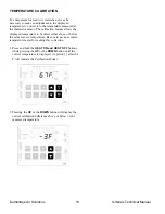
Page 66: ...output relay Separate settings for HEAT ON and HEAT OFF settings Temperature Calibration for accurate temperature control EEPROM storage maintains temperature settings indefinitely in case of power loss The thermistor enclosure SH 1 is packed inside the Remote Control Station for shipment It can be mounted on the exterior sides or bottom of the Remote Control Station or a remote location within 50...

Page 67: ...l the desired temperature for the heater to turn ON is displayed 2 Press and hold the HEAT OFF button while pressing the UP or the DOWN button until the desired temperature for the heater to turn OFF is displayed TEMPERATURE CALIBRATION To compensate for lead wire resistance it may be necessary to make an adjustment to the displayed temperature to correct it to the temperature measured at the ther...

Page 68: ...ic adjustment for Daylight Saving Time Nine Holiday Setback Periods for temporary setback operation Temperature Calibration for accurate temperature control Capacitor backup maintains current time and day of week for power loss of up to 96 hours EEPROM storage maintains schedules and temperature settings indefinitely The thermistor enclosure SH 1 is packed inside the Remote Control Station for shi...

Page 69: ... the DAY OF WEEK button while pressing the UP or the DOWN button until the light for the current day is illuminated 2 Press and hold the TIME button while pressing the UP or the DOWN button until the current time is displayed 3 Press and hold the MONTH DAY button while pressing the UP or the DOWN button until the current date is displayed 4 Press and hold the YEAR button while pressing the UP or t...

Page 70: ...he OFF time schedule is in effect See SETTING SCHEDULES for instructions on setting the ON and OFF schedules With the keyswitch in the SUMMER VENTILATION position the heater fan will run based on the time schedule with no temperature control HEATING MODE ON Time Schedule The HEATING mode requires two temperature settings When the temperature drops below the HEAT ON setting the heater will turn on ...

Page 71: ...y the VENT MODE light on the TSS Controller being illuminated Before attempting to program the schedule determine the planned time periods for HEAT ON and SETBACK OFF for the HEATING mode and the planned ON and OFF time periods for the Ventilation mode The time that it takes to recover from the SETBACK temperature to the HEAT temperature must also be taken into consideration for the ON time in the...

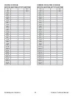
Page 72: ...4 On 5 Off 5 On 6 Off 6 On 7 Off 7 On 8 Off 8 On 9 Off 9 On 10 Off 10 On 11 Off 11 On 12 Off 12 On 13 Off 13 On 14 Off 14 SUMMER VENTILATION SCHEDULE Cycle Time AM PM Day On M F Off M F On 1 Off 1 On 2 Off 2 On 3 Off 3 On 4 Off 4 On 5 Off 5 On 6 Off 6 On 7 Off 7 On 8 Off 8 On 9 Off 9 On 10 Off 10 On 11 Off 11 On 12 Off 12 On 13 Off 13 On 14 Off 14 ...

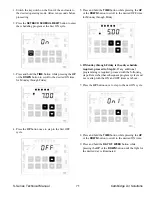
Page 73: ...s and bold the TIME button while pressing the UP or the DOWN button to scroll to the desired OFF time for Monday through Friday 6 If Monday through Friday is the only schedule required proceed to Step 14 If any additional programming is required proceed with the following steps Remember that subsequent program cycles must not overlap with the ON and OFF times set above 7 Press the UP button once t...

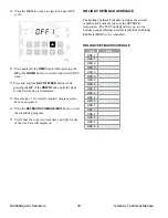
Page 74: ...red program cycles have been entered 14 Press the SETBACK SCHEDULE EXIT button to exit the scheduling program 15 Verify that the correct current time and light for day of the week are still displayed HOLIDAY SETBACK SCHEDULE The Holiday Setback Schedule overrides the normal schedule and holds the space at the SETBACK temperature The TSS Controller allows up to nine holiday periods Holiday Start Da...

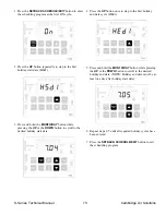
Page 75: ...the UP or the DOWN button to scroll to the desired holiday start date 4 Press the UP button once to step to the first holiday end date cycle HEd1 5 Press and hold the MONTH DAY button while pressing the UP or the DOWN button to scroll to the desired holiday end date NOTE Holiday end date must be at least one day after holiday start date 6 Repeat steps 2 5 until all required holiday cycles have bee...

Page 76: ...lows the displayed temperature to be offset either above or below the actual sensed temperature Be sure to use an accurate temperature meter for making this correction 1 Press and hold the HEAT ON and HEAT OFF buttons while pressing the UP or the DOWN button until the correct temperature is displayed A period after the F will indicate the Calibration Mode 2 Pressing the UP or the DOWN button will ...

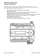
Page 77: ...ntrol of connected points BACnet MS TP compliant operating at up to 76 8 kilobaud BTL certified controller Standard input points for fan status burner status discharge temperature zone temperature outdoor temperature and unit lockout status Standard output points for fan control burner control and discharge temperature control Selectable operating modes unit heater makeup air summer ventilation Re...

Page 78: ...nals BLU WHT WHT FIG_EOLT_WRNG BLK BLU REF WHT Isolate and insulate the REF lead when connecting the EOL to third party devices with only and terminals 24V FC Bus NETWORK PARAMETERS Before operating controllers on a bus you must set a valid and unique device address for each controller on the bus through the local display or MAP gateway Device addresses 4 through 127 are the valid addresses for th...

Page 79: ...d Burner start 2 Discharge Temperature modulates to Discharge Set Point based on PID loop 3 If Zone Temperature is above Zone Set Point plus Differential then Supply Fan and Burner stop 4 Burner will not operate if Outdoor Temperature is above Heating Lockout Set Point SUMMER VENTILATION MODE 1 If Zone Temperature AI8 is above Zone Set Point AV4 then Supply Fan BO1 starts 2 If Zone Temperature AI8...

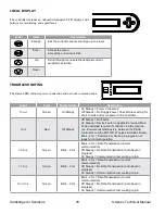
Page 80: ... No Faults On Steady Device Fault no application loaded Main Code download required if controller is in Boot mode or a firmware mismatch exists between the PEAK controllers and the ZRF1811 Wireless Field Bus Router Blink 2 Hz Download or Startup in progress not ready for normal operation SA Bus Green Blink 2 Hz Blink 2 Hz Data Transmission normal communication Off Steady No Data Transmission Auto ...

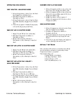
Page 81: ... be provided in a V bank filter section Filters may be of the disposable or permanent type Service the filters as needed based on the loading experienced Clean filters typically start out with a pressure drop across the filters between 0 15 and 0 25 WC Cleaning or replacement is generally required below the pressure drop increased by a factor of 4 times the initial clean value Turn off the heater ...

Page 82: ...on is extremely dirty or dusty it may become necessary to periodically clean the burner Remove and clean the burner in accordance with the following recommended procedures 1 Turn the heater disconnect switch off Close the manual gas supply shut off valve 2 Loosen the union in the gas train CAUTION The igniter is made of silicon carbide material and should be handled with care to avoid breakage 3 D...

Page 83: ... diaphragm assembly contacts the valve body and body gasket and the internal surface of the valve bonnet where the diaphragm assembly contacts the bonnet when the valve is in the energized open position IMPORTANT If the valve has been disassembled for inspection and cleaning only and a Rebuild Kit is not being installed lubricate the following with RemGrit TFL 50 Dry Lubricant Diaphragm assembly o...

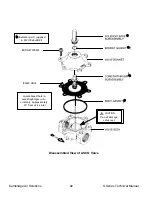
Page 84: ...s Technical Manual BONNET SCREW Indicates parts supplied in ASCO Rebuild Kit CAUTION Do not damage valve seat Locate bleed hole in core diaphragm sub assembly approximately 30 from valve inlet BLEED HOLE Disassembled View of ASCO Valve ...

Page 85: ...ply fusing b Replace control fuse c Replace transformer 7 Class 2 Transformer a No output voltage b Defective transformer a Check supply voltage b Replace transformer 8 Multi Functional PC Board a No input voltage on Terminal G RCS b Improper wiring c Defective board a Check voltage in RCS b Check wiring c Replace multi functional PC board 9 Damper Motor a Damper fuse tripped due to damper motor o...

Page 86: ...Y RELAY LOCKS OUT 1 Igniter a No current open igniter b No voltage During trial for ignition a Check igniter current b Check FSR output to igniter 2 High Limit a High limit tripped a See Problem Number VI page 86 3 High or Low Gas Pressure Switches a Low gas pressure switch tripped b High gas pressure switch tripped c Defective gas pressure switch a Check gas supply for low gas pressure or no gas ...

Page 87: ...g b Minimum fire set too low c Intermittent ground connection d Loose terminal on Flame Rod e Defective burner a Check manifold pressure b Adjust minimum fire on modulating valve c Tighten all ground points d Remove jam nuts from Flame Rod Reassemble with terminal located between jam nuts on Flame Rod e Replace burner 5 Flame Safeguard Relay a Defective FSR a Replace FSR 6 High Limit a High limit ...

Page 88: ...duce differential setting d Replace thermostat 2 Burner Service Switch a Switch in LOCAL position a Place switch in REMOTE position 3 Auxiliary Control a Auxiliary contacts closed a Check auxiliary circuit wiring and contacts 4 Misunderstood Control System Operation a Control system doesn t function as expected a Review control system operational characteristics VIII MODULATING VALVE DOES NOT MODU...

Page 89: ...Ω b Utilize shielded twisted pair wiring 6 Modulating Valve M511 M611 or MR212 a Foreign material holding valve open b Modulating valve misassembled a Disassemble valve and remove foreign material b Disassemble valve and assemble correctly IX MODULATING VALVE DOES NOT MODULATE CONTINUOUS LOW FIRE 1 Class 2 Transformer a No voltage output to amplifier a1 Check for short in modulating valve coil a2 ...

Page 90: ...inals 1 and 3 exceeds 12 000 Ω 7 Multi Functional PC Board a Terminal X has power b Defective board a Determine power source b Replace board X ERRATIC OR PULSATING FLAME 1 High Pressure Regulator a Vent undersized b Defective regulator a Enlarge vent piping size or reduce vent piping length b Replace regulator 2 Amplifier a Hunting b Temperature control system out of calibration c Defective amplif...

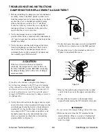
Page 91: ...ard or tripping of the onboard fuse may result If the fuse trips place the blower service switch in the OFF position for 15 seconds to allow fuse to reset Proceed with steps 4 through 10 PRIOR to connecting the damper motor to the linkage tube 4 Verify the cam location on the upper cam is set just short of the four o clock position with respect to the switch plunger being the twelve o clock refere...

Page 92: ...on The damper will open to the point the upper cam engages the upper limit switch 15 Remove the plastic plug from the damper viewport located on the exterior side of the heater housing toward the discharge end It may be helpful to place a flashlight inside the heater housing to observe the damper linkage tube travel to ultimately rest against the hex shaft 16 Using a deep well 1 2 hex socket or nu...

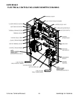
Page 93: ...S Series Technical Manual 91 Cambridge Air Solutions REFERENCE ELECTRICAL CONTROL ENCLOSURE ISOMETRIC DRAWING ...

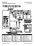
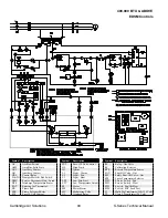
Page 94: ...hermostat FR Flame Rod FSR Flame Safeguard Relay Symbol Description FU1 Fuse 24 Volt Control FU2 Fuse 120 Volt Control HL High Limit IG Igniter L1 Light Alarm L2 Light Fan L3 Light Heat LTC Low Temperature Cutout M Motor MS Motor Starter MV Modulating Valve Symbol Description OL Overload Relay PCB Printed Circuit Board RTS Remote Temperature Sensor R1 Relay Gas Valve SOV Shut Off Valve Gas SW1 Ser...

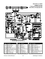
Page 95: ... Rod FSR Flame Safeguard Relay Symbol Description FU1 Fuse 24 Volt Control FU2 Fuse 120 Volt Control HL High Limit IG Igniter L1 Light Alarm L2 Light Fan L3 Light Heat LTC Low Temperature Cutout M Motor MV Modulating Valve MS Motor Starter Symbol Description OL Overload Relay RTS Remote Temperature Sensor R1 Relay Gas Valve SOV Shut Off Valve Gas SSV Safety Shut Off Valve Gas SW1 Service Switch Fa...

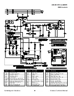
Page 96: ...use 24 Volt Control Symbol Description FU2 Fuse 120 Volt Control HL High Limit IG Igniter L1 Light Alarm L2 Light Fan L3 Light Heat LFS Low Fire Start LTC Low Temperature Cutout M Motor MS Motor Starter MV Modulating Valve OL Overload Relay Symbol Description R1 Relay Gas Valve RC Calibration Resistor RTS Remote Temperature Sensor SOV Shut Off Valve Gas SSV Safety Shut Off Valve Gas STS Space Temp...

Page 97: ...ontrol FU2 Fuse 120 Volt Control Symbol Description HL High Limit IG Igniter L1 Light Alarm L2 Light Fan L3 Light Heat LFS Low Fire Start LTC Low Temperature Cutout M Motor MS Motor Starter MV Modulating Valve OL Overload Relay OTS Override Timer Switch RC Calibration Resistor Symbol Description RTSS Remote Temperature Sensor R1 Relay Gas Valve SOV Shut Off Valve Gas SSV Safety Shut Off Valve Gas ...

Page 98: ...use 24 Volt Control Symbol Description FU2 Fuse 120 Volt Control HL High Limit IG Igniter L1 Light Alarm L2 Light Fan L3 Light Heat LFS Low Fire Start LTC Low Temperature Cutout M Motor MS Motor Starter MV Modulating Valve OL Overload Relay Symbol Description RHA Remote Heat Adjust RTS Remote Temperature Sensor R1 Relay Gas Valve SOV Shut Off Valve Gas SSV Safety Shut Off Valve Gas SW1 Service Swi...

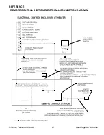
Page 99: ...S Series Technical Manual 97 Cambridge Air Solutions REFERENCE REMOTE CONTROL STATION ELECTRICAL CONNECTION DIAGRAM ...

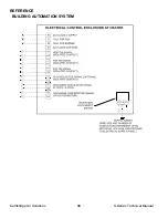
Page 100: ...Cambridge Air Solutions 98 S Series Technical Manual REFERENCE BUILDING AUTOMATION SYSTEM ...

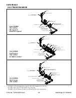
Page 101: ...T OFF VALVE ELECTRIC SHUT OFF VALVE SOV VALVE LEAK TEST MANOMETER TAP FOR LOW FIRE MANIFOLD PRESSURE ADJUSTMENT SCREWS UNDER COVER ELECTRIC SHUT OFF VALVE SSV MODULATING REGULATING VALVE MANIFOLD PRESSURE READING MANOMETER TAP FOR HAND SHUT OFF VALVE TO BURNER 1 Certified by CSA International to comply with ANSI Standard Z83 4 CSA3 7 2 Complies with Factory Mutual insurance requirements 3 Complies...

Page 102: ...d without Filter Section Low Pressure CSA Certified1 FM Compliant2 w VISUAL INDICATOR HAND SHUT OFF VALVE SUPPLY PRESSURE READING MANOMETER TAP FOR UNIT MANIFOLD PRESSURE ADJUSTMENT SCREW MANIFOLD PRESSURE REGULATOR MANOMETER TAP FOR MANIFOLD PRESSURE READING MANUAL RESET SWITCH HIGH GAS PRESSURE SWITCH MANOMETER TAP FOR VALVE LEAK TEST ELECTRIC SHUT OFF VALVE SSV TO BURNER ELECTRIC SHUT OFF VALVE...

Page 103: ...OV ELECTRIC SHUT OFF VALVE W VISUAL INDICATOR SSV ROOF SUPPORT BY OTHERS EXTERNAL GAS TRAIN ENCLOSURE HAND SHUT OFF VALVE SUPPLY PRESSURE READING MANOMETER TAP FOR UNIT MANUAL RESET SWITCH HIGH GAS PRESSURE SWITCH HAND SHUT OFF VALVE TO BURNER MANOMETER TAP FOR MANIFOLD PRESSURE READING MANOMETER TAP FOR VALVE LEAK TEST MANIFOLD PRESSURE LOW FIRE ADJUSTMENT SCREWS UNDER COVER MODULATING REGULATING...

Page 104: ...G REGULATING VALVE LOW FIRE MANIFOLD PRESSURE ADJUSTMENT SCREWS UNDER COVER VALVE LEAK TEST MANOMETER TAP FOR ELECTRIC SHUT OFF VALVE SOV MANOMETER TAP FOR UNIT SUPPLY PRESSURE READING HAND SHUT OFF VALVE ELECTRIC SHUT OFF VALVE SSV MANIFOLD PRESSURE READING MANOMETER TAP FOR HAND SHUT OFF VALVE TO BURNER HIGH GAS PRESSURE SWITCH MANUAL RESET SWITCH Over 400 MBH Low Pressure CSA Certified1 XL GAPS...

Page 105: ...ection of the ON and OFF temperatures This control can accommodate separately programmed schedules for both the ventilation and heating modes See the operating and programming instructions for the TSS Controller page 66 REMOTE CONTROL STATION COMPONENTS CLOGGED FILTER LIGHT CF The clogged filter light is an alarm light mounted in the remote control station to indicate a clogged filter condition In...

Page 106: ...temperature selector dial which is visible from the top of the RHA control increases the discharge temperature above the setting on the dial face by the increment selected 10 to 40 F when a jumper or switch contact is provided across terminals 20 and 22 Heaters which are specified with a temperature rise above 130 F are supplied with dual adjusting knobs on the dial face of the RHA This control pe...

Page 107: ...ouses the high limit HL and the discharge temperature sensor DTS This box should not be tampered with unless performing the Calibration Procedures pages 60 62 DISCHARGE TEMPERATURE SENSOR DTS The DTS is mounted in the discharge of the heater It senses the average discharge temperature and transmits a resistance signal back to the amplifier that corresponds to the discharge temperature FLAME ROD FR...

Page 108: ...pressure to build on the seat of the SSV safety shut off gas valve The gauge port between valves is used to determine if the SOV shut off gas valve seat is properly sealed MANIFOLD PRESSURE REGULATOR The manifold pressure regulator controls the burner manifold pressure When the MR212 valve is used this modulating valve also serves as the manifold pressure regulator The maximum gas supply pressure ...

Page 109: ...circuit by twisting the disconnect rod clockwise to assist in troubleshooting The disconnect rod must be turned back to the OFF position before attempting to secure the enclosure door EXHAUST FAN CONTACT EFC The exhaust fan contact is an auxiliary dry contact that is mechanically interlocked to the heater s motor starter and is provided with terminals located in the electrical enclosure The EFC is...

Page 110: ...lts This transformer provides the secondary control voltage of 24 and 115 Volts Heaters rated below 400 000 Btu hr or supplied for 115 Volts are furnished with the 24 Volt secondary transformer only Secondary fusing is provided in all Class I transformer circuits to protect the downstream components from short circuit Fuse sizing is as follows FNM 6 25 for 150 VA 24 Volt FNM 1 6 for 150 VA 115 Vol...

Page 111: ...w of all heaters exceeds 10 000 cfm The Cambridge TSS Controller with optimum start control will meet the standard A properly configured building DDC system with the necessary programming for zone control automatic shutdown setback and optimum start can also meet the standard Units intended to operate continuously No special controls are required to meet the standard Damper Section 6 4 3 4 3 A dam...

Page 112: ...Cambridge Air Solutions 110 S Series Technical Manual MAINTENANCE LOG MODEL NO SERIAL NO Date Activity Technician ...

Page 113: ...MAINTENANCE LOG MODEL NO SERIAL NO Date Activity Technician ...

Page 114: ...Cambridge Air Solutions 112 S Series Technical Manual ...

Page 115: ...ons modify the design and or substitute equivalent materials without notice as the result of code requirements product enhancements ongoing research development and vendor changes beyond our control SCAN THIS CODE TO ACCESS OUR HOW TO SERVICE VIDEOS ONLINE https www cambridgeair com parts service how to service videos ...

Page 116: ...760 Long Road Crossing Dr Chesterfield MO 63005 Phone 636 532 2233 800 899 1989 Fax 636 530 6133 www cambridgeair com ...

Reviews: