background image

8

Power syncing (On/Standby control)

:KHQJRLQJLQRXWRI6WDQGE\PRGHWKH$]XU(SUHDPSOLÀHUFDQLI

desired) automatically control the 851W when connected via the Control 
Bus sockets (the Control Bus sockets are colour-coded orange on the 
rear panels of compatible Azur models). For this feature to work the units 
must be connected together by RCA/phono leads. No futher setup is 
necessary. 

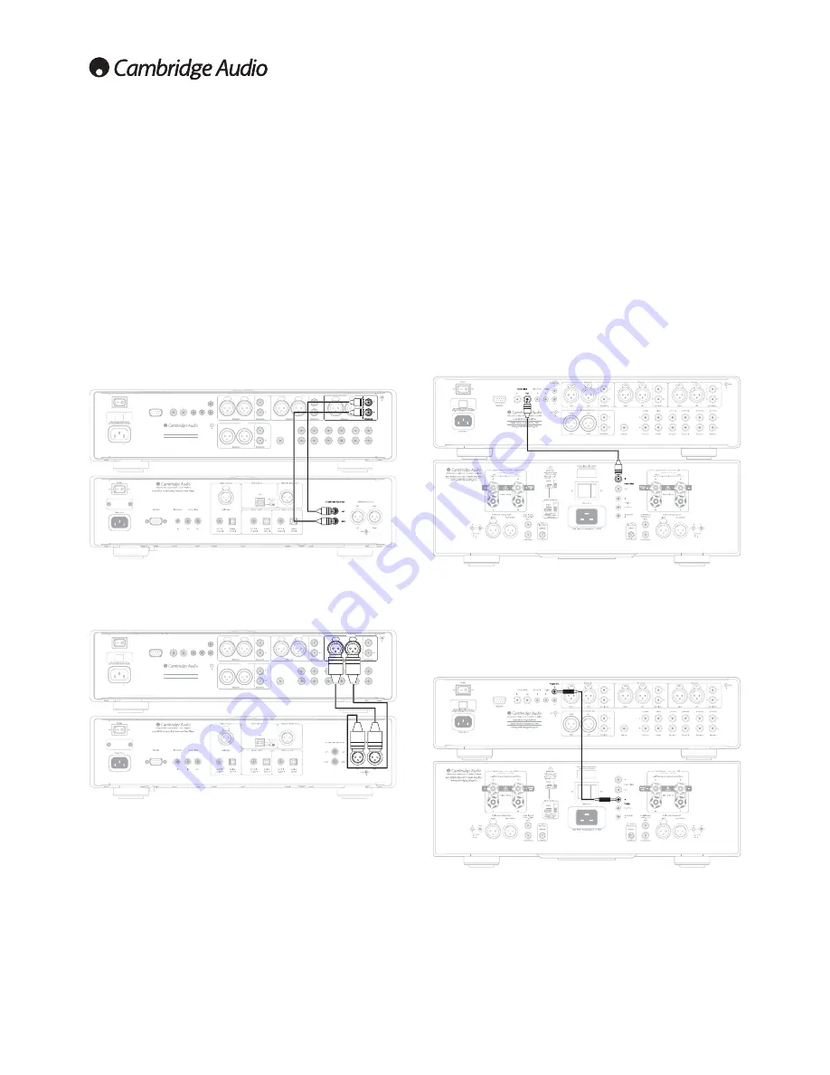
Connect the Control Bus Out from the 851E to the Control Bus In on the 
851W. Continue the chain to other Azur models if it is required to sync 
more units.

Note:

 The 851E features a Trigger Out which can alternatively be used to 

control the 851W's Standby/On status if desired. Again, the procedure is 
simply to connect the two units together (using a 3.5mm to 3.5mm mono 
mini-jack lead in this case).

Control Bus connection 

Control Bus is the recommended method when using an 851E and other 
Cambridge Audio equipment with Control Bus In/Out.

851E

851W

Trigger connection

Trigger In/Out can be useful if the 851W (and indeed 851E) is desired to 
be controlled by other equipment that features trigger outputs (Custom 
install and/or Multi-Room Systems etc). 

851E

851W

Source connections

Source 1, 2 and 3 on the 851E feature either unbalanced (phono/RCA) 
or balanced (XLR) connections. The 851E is designed to work at its 
highest performance when a balanced interconnect is used. 

7KH GLDJUDPV EHORZ VKRZ WKH ( SUHDPSOLÀHU FRQQHFWHG WR DQ

Azur 851C CD player in unbalanced (Figure 1) and balanced (Figure 2) 

FRQÀJXUDWLRQV7KH(FDQDOVREHFRQQHFWHGWRQRQ&DPEULGJH$XGLR

sources with balanced outputs.

Balanced connections in an audio system are designed to reject 
electrical noise, from power wiring etc, and also the effects of noise 

FXUUHQWV ÁRZLQJ WKURXJK JURXQG FRQQHFWLRQV 7KH EDVLF SULQFLSOH RI

balanced interconnection is to get the signal you want by subtraction, 
using a three-wire connection. One signal wire (the hot or in-phase) 
carries the normal signal, while other (the cold or phase-inverted) carries 
an inverted version. The balanced input senses the difference between 
the two lines to give the wanted signal. Any noise voltages that appear 
identically on both lines (these are called common-mode signals) are 
cancelled by the subtraction.

Power AC

R

L

R

L

Trigger Out

2

1

Trigger

In

In

In

Out

Re

c Out

Sub Out

Re

c In

Source

7

Sourc

e6

Sourc

e5

Sour

ce4

Rec Out

Rec In

Source 7

Source 6

Source 5

Source 4

RS232C

Control Bus

IR Emitter

GND

On

Off

Power

GND

azur 851E Pre-Amplifier

Rated Power Consumption

:

  36W

www.cambridge-audio.com

Designed and engineered in London, England

Left

Right

Source 3

Source 3

Left

Right

Source 2

Source 2

Left

Right

Source 1

Source 1

Left

Right

Left

Right

(Balanced)

(Unbalanced)

(Balanced)

(Unbalanced)

(Balanced)

(Unbalanced)

(Balanced)

(Unbalanced)

Pre Out

Pre Out

Source 1

(Unbalanced)

Figure 1: Unbalanced input

Phono/RCA

851E

851C

Power AC

R

L

R

L

Trigger Out

2

1

Trigger

In

In

In

Out

Re

c Out

Sub Out

Re

c In

Source

7

Sourc

e6

Sourc

e5

Sour

ce4

Rec Out

Rec In

Source 7

Source 6

Source 5

Source 4

RS232C

Control Bus

IR Emitter

GND

On

Off

Power

GND

azur 851E Pre-Amplifier

Rated Power Consumption

:

  36W

www.cambridge-audio.com

Designed and engineered in London, England

Left

Right

Source 3

Source 3

Left

Right

Source 2

Source 2

Left

Right

Source 1

Source 1

Left

Right

Left

Rig

ht

(Balanced)

(Unbalanced)

(Balanced)

(Unbalanced)

(Balanced)

(Unbalanced)

(Balanced)

(Unbalanced)

Pre Out

Pre Out

Left

Right

Source 1

(Balanced)

Figure 2: Balanced input

851E

851C

Summary of Contents for 851E

Page 1: ... rapide Comment configurer un systeme simple Guia rclpida Como configurar un sistema basico Avvio rapido Come configurare il sistema di base Snel starten Hoe u een basis systeem configureert Kom hurtigt i gang Sadan konfigureres et almindeligt system DbtCTpa ycTaHOBKa KaK CKOHtPHrypHpOB3Tb OCHOBHYIO KaHaflbHYIO CHCTeMy 8 CambridgeAudio ...

Page 2: ... the box Lieferumfang Que contient Ia boite Contenido de Ia caja Cosa contiene Ia confezione Wat u in de doos zult vinden Hvad er der i kassen 4TO B KOp06Ke 8 CambridgeAudio azur 851E 0 ooo ooo 000 000 0 000 0 0 ...

Page 3: ...o lnstalacion Conflgureren HacTpolliKa azur lmpostazloni Opsatning 851W Class XD power amplifier No deje de leer el manual Contiene toda Ia informaciOn necesaria para obtener el maximo rendlmiento de su equipo Azur 851E I851W Per ottenere le migliori prestazioni dal dispositive Azur 851E 851W leggere attentamente il manuale perle relative informazioni Om de beste prestatles van uw Azur 851E 851W t...

Page 4: ...acion acerca de Cambridge Audio nuestros productos noticias resenas y soporte visite Per maggiori informazioni su Cambridge Audio e i nostri prodotti per notizie articoli e assistenza visitare Voor meer informatie over Cambridge Audio onze producten nieuws beoordelingen en support ondersteuning kunt u onze website bezoeken Du kan finde flere oplysninger om Cambridge Audio vores produkter nyheder o...

Page 5: ...Your music our passion 851E azur 3UH PSOLÀHU User s manual 2 ENGLISH ...

Page 6: ...anual may be reproduced by any mechanical electronic or other means in any form without prior written permission of the manufacturer All trademarks and registered trademarks are the property of their respective owners Copyright Cambridge Audio Ltd 2013 Cambridge Audio and the Cambridge Audio logo are trademarks of Cambridge Audio Other brands mentioned are trademarks of their respective owners and...

Page 7: ...y air inlets or outlet grilles Do not cover the ventilation grilles with items such as newspapers tablecloths curtains etc This unit must not be used near water or exposed to dripping or splashing ZDWHU RU RWKHU OLTXLGV 1R REMHFWV ÀOOHG ZLWK OLTXLG VXFK DV YDVHV VKDOO be placed on the unit Important safety instructions 7KH OLJKWQLQJ ÁDVK ZLWK WKH DUURZKHDG V PERO ZLWKLQ DQ HTXLODWHUDO triangle is ...

Page 8: ... 7KH FRORXUV RI WKH ZLUHV in the mains lead of this appliance may not correspond with the coloured markings identifying the terminals in your plug Connect them as follows The wire which is coloured BLUE must be connected to the terminal which is marked with the letter N or coloured BLACK The wire which is coloured BROWN must be connected to the terminal which is marked with the letter L or coloure...

Page 9: ... on off some Cambridge Audio units LQFOXGLQJ WKH PDWFKLQJ SRZHU DPSOLÀHU 5HIHU WR WKH 3RZHU syncing section of this manual for more information 6 IR Infra Red Emitter In Allows modulated IR commands from multi room systems or IR repeater systems to be received by the unit Commands received here are not looped out of the Control Bus Refer to the Custom installation section of this manual for more i...

Page 10: ...ponent that you wish to listen to highlighted by a solid circle on the display The signal selected is also fed to the Rec Out sockets so that it may be recorded The input should not be changed whilst recording but the recorded signal can be checked using the Rec input Note Repeatedly pressing the Source 1 2 or 3 buttons will toggle these inputs between Balanced and Unbalanced source input 7KH VROL...

Page 11: ...ed by Mute appearing and the volume level being UHSODFHG E WZR ÁDVKLQJ GDVKHV LQ WKH GLVSOD 3UHVV again to cancel mute 4 Volume QFUHDVH RU GHFUHDVH WKH YROXPH RI WKH DPSOLÀHU RXWSXW 5 Illuminate button Press to illuminate the buttons on the remote 6 S1 S8 Sources Used to select the source inputs 7 Source Direct Press to give the audio signal a more direct path to the SRZHU DPSOLÀHU VWDJH RI RXU DP...

Page 12: ...ned to reject electrical noise from power wiring etc and also the effects of noise FXUUHQWV ÁRZLQJ WKURXJK JURXQG FRQQHFWLRQV 7KH EDVLF SULQFLSOH RI balanced interconnection is to get the signal you want by subtraction using a three wire connection One signal wire the hot or in phase carries the normal signal while other the cold or phase inverted carries an inverted version The balanced input sen...

Page 13: ...ency For single wiring it is recommended to connect to the LF terminals The metal strip connecting the low frequency terminals to the high frequency terminals must not be removed only to be removed for a bi wiring system Note Q WKLV FRQÀJXUDWLRQ WKH PXVW EH VHW WR 6WHUHR PRGH 851E 851W Output connections Unbalanced The 851E features both balanced XLR and unbalanced RCA Phono output connections For...

Page 14: ...nt 851W settings Before making any connections to the loudspeakers make sure all power is turned off and only use suitable interconnects e g banana plugs Ensure that the positive and negative connections are wired as shown in the diagram When using balanced XLR connections the Left and Right Input Type switches on the 851W must be in the Balanced position When using unbalanced phono RCA connection...

Page 15: ...ce 6 Source 7 Rec In The 851E stores whether direct mode is on or off for each input individually for example it is possible to have the tone controls automatically active for the Tuner source but not the CD source 3UH DPSOLÀHU VHWXS The 851E features many advanced settings that allow its use to be FXVWRPLVHG WR XVHU SUHIHUHQFH 7KH LQSXWV FDQ EH QDPHG WR UHÁHFW WKH actual source units you have eac...

Page 16: ...bled The relative levels of the inputs can be adjusted by gain trim This allows each to be adjusted so that each sounds the same in terms of average loudness when you switch between them Pick the loudest sounding source and trim its level until it matches the average perceived level of the others Repeat this process if other sources also stand out as louder than the average To set the input gain t...

Page 17: ...ble the IR function by setting IR to off In the System settings menu press the Control input select button to enter the submenu Pressing the IR input select button will scroll through the IR enabled options of Front Back Front Back and IR IC disable front and back IR Press the Mode button to exit the submenu Mode Volume Frn Bck Control C Bus RS232C In the System settings menu press the Control inp...

Page 18: ...Standby 3 W Overload Overvoltage overcurrent detection Indicator Unit has switched off during operation Description CAP5 offers V I protection by constantly monitoring the output transistors to keep them working inside their Safe Operating Area SOA The SOA is a set of limits given by the output transistor PDQXIDFWXUHU WR HQVXUH UHOLDELOLW 9 DOVR SURWHFWV WKH DPSOLÀHU DJDLQVW short circuits on the ...

Page 19: ...utput 8V rms unbalanced 8V 8V rms balanced Output impedence 100 Ohms Unbalanced or Balanced Subwoofer out Flat or 200Hz 2nd Order Butterworth LPF Max power consumption 36W Bass Treble controls Shelving type Max bass boost cut 10 dB at 10 Hz Max treble boost cut 7 5 dB at 20 kHz Dimensions H x W x D 115 x 430 x 385mm 4 5 x 16 9 x 15 2 Weight 8 1kg 17 9Lbs 7HFKQLFDO VSHFLÀFDWLRQV The 851E features a...

Page 20: ...idge Audio is a brand of Audio Partnership Plc 5HJLVWHUHG 2IÀFH DOOHU RXUW DQNH 3ODFH London SE1 4BB United Kingdom Registered in England No 2953313 www cambridge audio com 2013 Cambridge Audio Ltd AP32333 1 ...

Reviews: