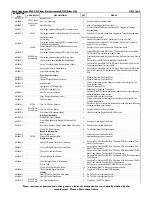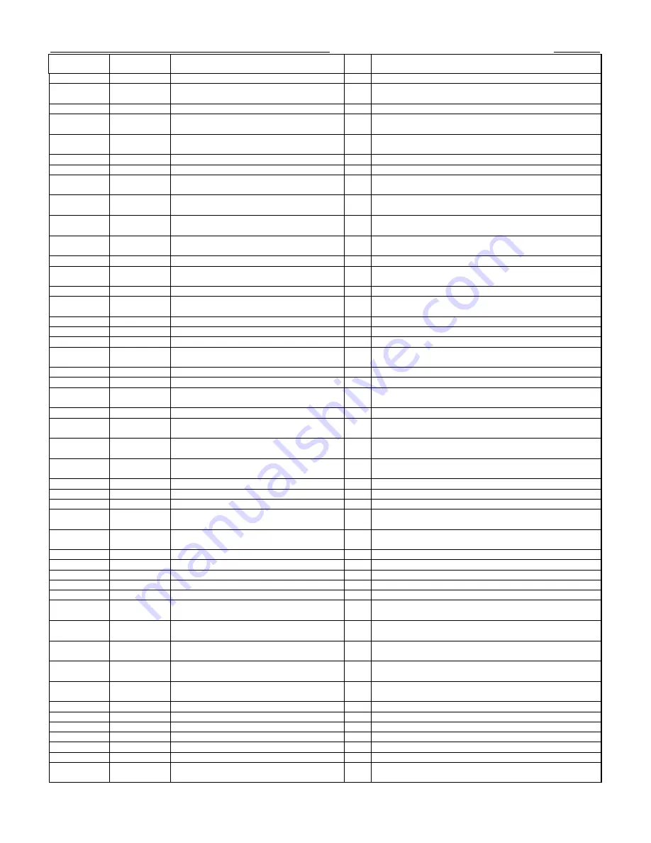
AP15162/2
AP DRAWING
NO
AP PART NO
DESCRIPTION
QTY
NOTES
AP12735/5
Bottom Panel
1
AP12652/2
PY531 - Black
PY541 Silver
Azur Foot Moulding
4
Position In Place on Bottom Panel
AP12883/3
PY544
Azur Foot Pad
4
Affix on Foot Using Adhesive Surface
AP13571/1
Cambridge Audio New Range CD Transformer Pad
1
Position In Place On Bottom Panel With The Fixing Bolts Through
Supplied Holes
AP13157/3
PY563
Cambridge Audio EI 115/230v 540c/640c Transformer
1
Position On Transformer Pad With Fixing Bolts Through Supplied Holes
Heatshrink sleeve
70mm For transformer wires
Ferrite Ring
1
Added to secondary wires of transformer (3 turns x 3 wires)
AP13545/1
Cambridge Audio New Range CD Transformer Can
With Adhesive Pad Added
1
Screened With Artwork AP13721/1 Position On Top Of Transformer
And Press To Stick In Place
PY340
Yanion Version Of Sony CD Mech With Sony Laser
Block (PY790)
1
Position In The Correct Position On The Bottom Panel
AP13544/3
Cambridge Audio New Range CD Mech Top Sticker
1
Screened With Artwork AP13763/1. Then Position Over Locating Pips
On CD Mech Top Surface And Press To Stick
AP13495/1
PY568 Silver
PY554 Black
Cambridge Audio New Range CD Draw Front
1
Screened With Artwork AP13601/1 Position On Draw Front And Glue In
Place
AP13617/1
16 Way Laser Cable, Flexible Flat Cable 250mm
1
Connects Servo PCB To Laser Block On The CD Mech
AP13618/1
5 Way Tray Motor Cable Flat Wire Style 350mm
1
Connects The Servo PCB To The CD Mech, Runs Under The Front Of
The Mech And Under The Servo PCB
AP13619/1
6 Way Spindle Motor Cable 200mm
1
Connects The Servo PCB To The CD Mech, Runs Under The CD Mech
AP13895/1
Mains PCB Insulating Sheet
1
Cut to fit 2 standoffs. To Be Positioned Over Standoffs Under Power
PCB
Front Panel Assembly
AP12935/1
IR Lens
1
Glued In Place On The Front Panel
AP13322/2
105mm Display Window (Mirrored)
1
Glued In Place On The Front Panel
AP13436/2
Sub Panel Left
1
Fasten in place between the Ledges of the Front Panel, Align Up The
Power Button Holes
AP12931/1
Lightguide, Cut To Single Pipe
1
Fasten To Subplate Left
M3 X 6 Pozi Pan Stp Screw
1
Affixes Single Lightguide To Subplate
AP13585/1
9mm TAC Switch Cushion
1
Position on the 9mm tact switch button, down the main shaft affix using
adhesive provided on the cushion.
AP11782/1
Opus Control Box Button (9mm)
1
Position in Place on the Front Panel
AP13437/2
Sub Panel Right
1
Fasten in place between the Ledges of the Front Panel, Align Up The
Function Button Holes
AP12934/1
PY704
7mm TAC Switch Cushion
5
Position on the 7mm tact switch Buttons, down the main shaft affix using
adhesive provided on the cushion.
AP12925/1
PY719 Black
PY720 Silver
7mm TAC Switch Button
5
Position In Place On The Front Panel
AP13578/3
Front Panel PCB Assembly BOM
1
Fixes onto the Sub Panels With M3 M/C Screws
Side Panel Assembly
AP12725/2
Pressed Side Panel (2 Ridge)
2
AP12727/1
Front Plastic Support (2 Ridge With Captive M2.6
Nuts)
2
Position at Front within Side Panels
AP12728/1
Rear Plastic Support (2 Ridge With Captive M2.6 Nuts)
2
Position at Rear within Side Panels
M2.6 X 8 C/S Pozi Plastite
8
To Affix Side Panels To Plastic Inserts
Rear Panel Assembly
AP13435/2
Rear Panel Printed
1
Screened With Artwork AP14835/1
AP14647/2
PY789
Output PCB Assembly BOM
1
Mounted directly on the rear panel
Final Assembly
AP13620/1
8 Way LCD Cable, Flat Wire Style 280mm
2
Connects The Front Panel PCB To The Servo PCB, Runs Around The
Side Of The Casework
AP13621/1
7 Way LCD Cable, Flat Wire Style 500mm
1
Connects The Front Panel PCB To The Servo PCB, Runs Around The
Side Of The Casework
AP13622/1
7 Way Control Cable 520mm
1
Connects The Front Panel PCB To The Servo PCB, Runs Under The CD
Mech Then Around The Outside Of The Casework
AP13623/1
3 Way Standby Cable 380mm
1
Connects The Front Panel PCB To The Stand By PCB, Runs Underneath
The CD Mech
AP13624/1
2 Way Backlight Power Cable 440mm
1
Connects The Front Panel PCB To The Servo PCB, Runs Under The CD
Mech Then Around The Outside Of The Casework
Ferrite Tube
1
Fit ferrite over screened cables, CN2 & CN3 on output PCB
M2.6 X 6 Pozi Pan Machine Screw
15
To fix Bottom Panel To Side, Front And Rear Panels
AP13626/1
3 Way Shielded Digital Out Cable
2
From DAC PCB to rear panel PCB assembly
Lidding
AP13340/1
Lidding Tape For Front And Rear Panels
2
Fix To The Correct Surfaces For Lid
AP13342/1
Lidding Tape For Side Panels
2
Fix To The Correct Surfaces For Lid
AP12733/2
PY507 Black
PY508 Silver
Top Panel Without Vents
1
Position on Top Of The Product
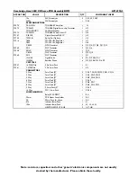
Cambridge Azur 340C CD Player Main Assembly BOM (Silver UK)
Note: resistors, capacitors and other 'generic' electronic components are not usually stocked by the
manufacturer. Please obtain these locally.
Summary of Contents for Azur 340C
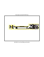
Page 7: ...Cambridge Audio Azur 340C CD Player AP12992 3 Front Panel PCB Layout Top Side ...
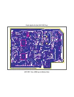
Page 8: ...Cambridge Audio Azur 340C CD Player AP12992 3 Front Panel PCB Layout Bottom Side ...
Page 10: ...Cambridge Audio Azur 340C CD Player AP14644 4 Output PCB Layout Top Side ...
Page 11: ...Cambridge Audio Azur 340C CD Player AP14644 4 Output PCB Layout Bottom Side ...
Page 13: ...Cambridge Audio Azur 340C CD Player AP13637 4 Mains PCB Layout Top Side ...
Page 14: ...Cambridge Audio Azur 340C CD Player AP13637 4 Mains PCB Layout Bottom Side ...
Page 17: ...Cambridge Audio Azur 340C CD Player AP12927 7 Servo PCB Layout Top Side ...
Page 18: ...Cambridge Audio Azur 340C CD Player AP12927 7 Servo PCB Layout Bottom Side ...
Page 25: ...Cambridge Audio Azur 340C CD Player IC Pin Layout Details Control PCB PIC16C505 U3 TSOP18 U2 ...
Page 26: ...Output PCB APTX179AT U1 74HC14 U2 ...
Page 27: ...SERVO PCB TA2153FN U1 TC9462F U2 ...
Page 28: ...TLCS 870 MCU U3 TA2092 U6 ...

