background image

2


.

Contents

For your own safety please read the following important safety 

instructions carefully before attempting to connect this unit to the mains 

power supply. They will also enable you to get the best performance from 

and prolong the life of the unit:
  1. Read these instructions.
  2. Keep these instructions. 
  3. Heed all warnings. 
  4. Follow all instructions. 
  5. Do not use this apparatus near water. 
  6. Clean only with a dry cloth. 
  7.  Do not block any ventilation openings. Install in accordance with the 

manufacturer’s instructions.

  8.  Do not install near any heat sources such as radiators, heat registers, 

stoves, or other apparatus (including amplifiers) that produce heat. 

  9.  Do not defeat the safety purpose of the polarized or grounding-type 

plug. A polarized plug has two blades with one wider than the other.  

A grounding-type plug has two blades and a third grounding prong.  

The wide blade or the third prong are provided for your safety. If the 

provided plug does not fit into your outlet, consult an electrician for 

replacement of the obsolete outlet. 

10.  Protect the power cord from being walked on or pinched, particularly 

at plugs, convenience receptacles and the point where they exit from 

the apparatus. 

11.  Only use attachments/accessories specified by the manufacturer. 
12.  Use with only the cart, stand, tripod, bracket, or table 

specified by the manufacturer, or sold with the apparatus. 

When a cart is used, use caution when moving the cart/ 

apparatus combination to avoid injury from tip-over.

13.  Unplug this apparatus during lightning storms or when unused for 

long periods of time. 

14.  Refer  all  servicing  to  qualified  service  personnel.  Servicing  is 

required when the apparatus has been damaged in any way, such 

as the power-supply cord or plug having been damaged, liquid has 

been spilled or objects have fallen into the apparatus, the apparatus 

has been exposed to rain or moisture, does not operate normally, or 

has been dropped.

WARNING 
–  To reduce the risk of fire or electric shock, do not expose this unit to 

rain or moisture. 

–  Batteries (battery pack or batteries installed) shall not be exposed to 

excessive heat such as sunshine, fire or the like.

The unit is of Class 1 construction and must be connected to a mains 

socket outlet with a protective earthing connection.
The unit must be installed in a manner that makes disconnection of 

the mains plug from the mains socket outlet (or appliance connector 

from the rear of the unit) possible. Where the mains plug is used as the 

disconnect device, the disconnect device shall remain readily operable. 

Only use the mains cord supplied with this unit.
Please ensure there is ample ventilation (at least 10cm clearance all 

round). Do not put any objects on top of this unit. Do not situate it on 

a rug or other soft surface and do not obstruct any air inlets or outlet 

grilles. Do not cover the ventilation grilles with items such as newspapers, 

tablecloths, curtains, etc.
This unit must not be used near water or exposed to dripping or splashing 

water or other liquids. No objects filled with liquid, such as vases, shall 

be placed on the unit.

Important safety instructions

Important safety instructions .....................................................................2
Rear panel connections ..............................................................................4
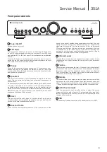
Front panel controls ....................................................................................5
Remote control ............................................................................................6
Connections .................................................................................................7
Technical specifications ..............................................................................9
Troubleshooting ...........................................................................................9
Packaging exploded diagram .................................................................. 10
Front panel exploded diagram ................................................................ 10
Unit exploded diagram ............................................................................. 11
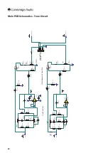
Main PCB Schematics - Tone Circuit ....................................................... 12
Main PCB Schematics - Power Amps ...................................................... 13
Main PCB Schematics - Power Supply .................................................... 14
Main PCB Schematics - iPod Stage......................................................... 15
Main PCB Schematics - Parts for Bom ................................................... 16
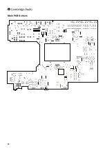
Main PCB Gerbers .....................................................................................17
Main PCB BOM ......................................................................................... 18
Main PCB BOM ......................................................................................... 20
Microcontroller PCB Schematics ............................................................. 22
Microcontroller Gerbers ........................................................................... 23
Microcontroller PCB BOM .........................................................................24
USB PCB Schematic ................................................................................. 25
USB PCB Gerber ....................................................................................... 26
USB PCB BOM ...........................................................................................27
IC details ................................................................................................... 29

Summary of Contents for AZUR 351A

Page 1: ...r Inputs 5 x RCA 1 x USB type B 1 x 3 5mm MP3 input Outputs Speakers A B 1 x Rec Out headphone out USB USB audio 1 0 16 bit 32kHz 44 1kHz 48kHz Frequency Response 5Hz 50kHz S N ratio ref 1w 92dB unweighted Input Impedance 47k ohms Max Power Consumption 320W Bass Treble controls Shelving ultimate boost cut 10dB 20Hz and 6dB 20kHz Dimensions H x W x D 86 x 430 x 340mm 3 4 x 16 9 x 13 4 ...

Page 2: ...s been spilled or objects have fallen into the apparatus the apparatus has been exposed to rain or moisture does not operate normally or has been dropped WARNING To reduce the risk of fire or electric shock do not expose this unit to rain or moisture Batteries battery pack or batteries installed shall not be exposed to excessive heat such as sunshine fire or the like The unit is of Class 1 constru...

Page 3: ...TV technician for help Ventilation IMPORTANT The unit will become hot when in use Do not stack multiple units on top of each other Do not place in an enclosed area such as a bookcase or in a cabinet without sufficient ventilation Ensure that small objects do not fall through any ventilation grille If this happens switch off immediately disconnect from the mains supply and contact your dealer for a...

Page 4: ...l loudspeaker to the LEFT positive and negative terminals and the wires from the right channel loudspeaker to the RIGHT positive and negative terminals In each case the red terminals are the positive outputs and the black terminals are the negative outputs Care should be taken to ensure no stray strands of wire are shorting speaker outputs together Please ensure that the loudspeaker terminals have...

Page 5: ...ircuits for the purest possible sound quality 6 Bass and Treble These controls allow subtle adjustments to the tonal balance of the sound In the central position these controls have no effect They only modify the sound through your loudspeakers and do not affect the signals sent through the Rec Out connections With a well produced CD and a good system the tone controls are unnecessary and can be s...

Page 6: ...ind Information Used with CDs that support CD text In stop mode press to toggle between album name and total time on the display During playback press to toggle between track name and track time Bright Alters the brightness of the 351C display backlight There are three levels of brightness Bright Dim and Off Program Remain Repeat Random Read the Operating Instructions section of the Azur CD manual...

Page 7: ...am below shows how to connect the amplifier to a tape recorder or other component with a record function Please note that either of the record outputs can be used as they are both the same signal in parallel Note All connections are made using standard loudspeaker cable Basic connection The diagram below shows the basic connection of your unit to a CD player and a pair of loudspeakers Right Left R...

Page 8: ...her and computer types without drivers and allows 16 bit audio at 32kHz 44 1kHz and 48kHz to be received Note When using two pairs of speakers use speakers with a minimum nominal impedance of 8 ohms each The 351A also works with most distributions of Linux using the native Audio 1 0 driver Because Linux distributions vary according to their creator s choice of software components including drivers...

Page 9: ...le to make play tape recordings Check that Rec Out have been connected correctly There is weak bass or diffused stereo imaging Ensure that speakers are not wired out of phase The sound is distorted Check that the volume or tone controls are not set too high The remote handset will not function Check that the batteries have not expired Ensure that nothing is blocking the remote sensor In the event ...

Page 10: ...10 Packaging exploded diagram 1 1 Drawing ref Part number Description 1 PDA019 Remote control Drawing ref Part number Description 1 PY1764 Front panel PCB Front panel exploded diagram ...

Page 11: ...Description 1 PY1758 Wrapover lid black colour 1 PY1760 Wrapover lid silver colour 2 PY1766 Toroid transformer 115V to 230V 3 PDA015 USB input PCBA 4 PDA014 Amplifier PCBA 5 PY1762 Volume board 6 PZ725 Front panel black colour 6 PZ726 Front panel silver colour 2 1 6 4 5 3 ...

Page 12: ... Polyester C15 10pF 50V NP0 Ceramic SW1 B 2P2T Pushbutton Switch DEFEAT C16 Met Polyester 47nF 63V C17 Met Polyester 47nF 63V 2 3 1 8 4 U2 A NE5532P Audio Op Amp 6 5 7 U2 B NE5532P Audio Op Amp R SEL OUT L SEL OUT POWER AMP RIGHT POWER AMP LEFT R52 1 4W Metal Film 150k R54 1 4W Metal Film 150k R59 1 4W Metal Film 150k R60 1 4W Metal Film 150k 4 6 5 VR4 B MN20k Balance Pot 1 3 2 VR4 A MN20k Balance...

Page 13: ...470R 1W Metal Film 1 2 CN2 A Loudspeaker 4 3 CN2 B Loudspeaker 5 6 CN2 C Loudspeaker 8 7 CN2 D Loudspeaker LEFT SPEAKER A LEFT SPEAKER B RIGHT RIGHT 3 4 5 RL1 B ME11 012 2Z4 2P2T Relay 6 7 8 RL1 C ME11 012 2Z4 2P2T Relay 1 2 RL1 A ME11 012 2Z4 360R Q3 BC337 25 NPN Signal D9 Rectifier 1N4002 R75 220R 1 2W Metal Film 20V R76 4k7 1 4W Metal Film OUTPUT RELAY R77 100k 1 4W Metal Film R78 100k 1 4W Met...

Page 14: ...O 3 GND 2 U5 7805 Regulator C47 47uF 16V Electrolytic C48 Met Polyester 47nF 63V VI 1 VO 3 GND 2 U8 L7815 Regulator VI 2 VO 3 GND 1 U9 L7915 Regulator C49 100uF 25V Electrolytic C50 100uF 25V Electrolytic 5V C51 47nF 63V Met Polyester C52 Met Polyester 47nF 63V C53 Met Polyester 47nF 63V 15V 15V FROM TRANSFORMER 20V J3 J4 J8 OPAMP SUPPLY MICROCONTROLLER SUPPLY POWER AMP SUPPLY C28 470nF Mains Rate...

Page 15: ...SEL OUT 6 5 7 U3 B NE5532P Audio Op Amp R94 91R 2W Metal Film 15V R95 1k 1 2W Metal Film SHIELD GND IPOD_L IPOD_R R96 1 4W Metal Film 100k R97 1 4W Metal Film 100k R89 62k 1 4W Metal Film R88 1 4W Metal Film 3k9 R87 1 4W Metal Film 100k 1 2 3 4 5 6 CN11 FOR 340A SE FIT ALL COMPONENTS EXCEPT LK506 LK507 FOR 340A ONLY FIT LK506 LK507 DO NOT FIT OTHER COMPONENTS FIT ONLY FOR 340A FIT ONLY FOR 340A ip...

Page 16: ...16 Main PCB Gerbers ...

Page 17: ...351A Service Manual 17 Main PCB Gerbers ...

Page 18: ...18 Main PCB Gerbers ...

Page 19: ...351A Service Manual 19 Main PCB Gerbers ...

Page 20: ...al Film 5 R2 R3 R42 R43 R76 1 10mm Pitch 14 8k2 1 4W Metal Film 4 R4 R11 R44 R45 1 10mm Pitch 15 10k 1 4W Metal Film 5 R33 R36 R85 1 10mm Pitch 16 22k 1 4W Metal Film 4 R1 R20 R58 R70 1 10mm Pitch 17 27k 1 4W Metal Film 4 R9 R57 R66 R69 1 10mm Pitch 18 47k 1 4W Metal Film 4 R71 R74 1 10mm Pitch 19 62k 1 4W Metal Film 2 R89 R93 1 10mm Pitch 20 100k 1 4W Metal Film 10 R37 R40 R77 R78 R87 R91 R96 R97...

Page 21: ... 1 C91 10 5mm Pitch 40 47nF 63V Met Polyester 12 C4 C5 C7 C8 C16 C17 C48 C51 C53 C75 C76 10 5mm Pitch Box 41 100nF 100V Mono Ceramic 4 C2 C26 C36 C44 10 5mm Pitch 42 100nF 100V Mono Ceramic 3 C84 C85 C98 10 5mm Pitch 43 150nF 63V Polyester 2 C6 C11 5mm Pitch Box 44 470nF Mains Rated X2 1 C28 22 5mm Pitch Box 45 10uF 35V NP Electrolytic 22 C3 C14 C18 C21 C25 C30 C31 C33 C37 C54 C57 C60 C66 C78 C80 ...

Page 22: ...D10 D15 1N4148 D035 67 5 1V Zener 1 D16 BZX85 C5V1 DO41 68 Blue Azur LED 3mm 1 D18 HFB963M 130 FUSES Value Description Type Qty Component Ident ManPN Tolerance PackageInfo AP Numbers 69 T6 3AL Slow Blow Fuse 3 F1 F2 F6 20mm 70 T1AL Slow Blow Fuse 2 F4 F5 20mm INDUCTORS 71 1uH Ferrite On 24AWG Wire 2 FB1 FB2 RES7 5MM 72 24 5T 0 9mm Output Inductor 2 L1 L2 CS79 874967 Through Hole INTEGRATED CIRCUIT...

Page 23: ...82 Mains Rated Power Switch 1 SW3 KDA A04 10 TRANSISTORS Value Description Type Qty Component Ident ManPN Tolerance PackageInfo AP Numbers 83 45V 500mA PNP Signal 2 Q1 Q4 BC327 25 TO92 PY219 84 45V 300mA NPN Signal 4 Q2 Q3 Q5 Q6 BC337 25 TO92 PY214 Note Resistors capacitors and other generic components are not usually stocked by the manufacturer Please obtain these locally ...

Page 24: ...Please obtain these locally Volume Control PCB BOM RESISTORS VARIABLE Value Description Type Qty Component Ident ManPN Tolerance PackageInfo Service Part Numbers 1 50k log ALPS volume pot with motor 1 VR1 RK16812MG082 16mm Motorised Volume Pot PY1603 CAPACITORS Value Description Type Qty Component Ident ManPN Tolerance PackageInfo AP Numbers 2 10nF 50V Ceramic 1 C1 1N5402 10 2 5mm Pitch MISCELLANE...

Page 25: ... 1 4W Metal Film C26 100nF 100V Mono Ceramic L CH IN R CH IN R50 270k 1 4W Metal Film R51 1 4W Metal Film 270k LEFT RIGHT iPod USB iPod USB 5V MUTE MICROCONTROLLER BOARD CONNECTOR OUTPUT RELAY DC OFFSET DATA CLOCK STROBE 2 3 5 6 A B C D L R L R TAPE OUT R AUX R CD TUNER DAB DVD AV MD AUX L CD TAPE OUT L TUNER DAB DVD AV MD B T B T Vss 1 L S1 2 L S2 3 L S3 4 L COM1 5 L S4 6 L S5 7 L S6 8 L COM2 9 L...

Page 26: ...26 Note Resistors capacitors and other generic components are not usually stocked by the manufacturer Please obtain these locally Microcontroller Gerbers ...

Page 27: ...16F882 I SP MicroController 1 U1 Programmed with AP26584 XX 7 BA6218 Motor Controller 1 U2 PY260 DIODES Value Description Type Qty Component Ident AP Numbers 8 3100 000030 003 Blue Flat top LED 6 D1 D6 Please use flat top LED at standard Azur height PY064 CONNECTORS Value Description Type Qty Component Ident AP Numbers 9 ICP Picoplex PF 50 6 way male header 1 CN1 Vertical 6 way male header 10 H9 2...

Page 28: ...28 USB PCB Schematic Note Resistors capacitors and other generic components are not usually stocked by the manufacturer Please obtain these locally ...

Page 29: ... U4 C49 C50 C7 C8 R18 C35 R10 C21 R23 C1 C2 C3 C4 C6 C11 C5 C16 FB10 C14 R4 R7 R9 R24 R42 R1 R2 R12 R13 C15 C17 C9 C10 R40 C13 R6 C12 R14 C22 C23 C25 C24 R15 R16 U1 R3 P1 P2 FB2 R25 R22 C31 2011 R5 R8 R27 R11 C27 U3 C33 D1 R28 R19 C28 R20 Q1 R29 Q2 R31 R30 R32 C32 C18 C19 C20 C26 C30 Q3 Q5 Q6 R17 R21 R33 R34 R43 R44 R45 R26 Q4 AUDIO PARTNERSHIP R36 R35 R37 C29 C44 C45 C AP30309 1 ...

Page 30: ...Thick Film 1 R4 1 0603 CAPACITORS Value Description Type Qty Component Ident ManPN Tolerance PackageInfo AP Number 14 33K RESISTOR 0603 Thick Film 1 C15 1 0603 As per R21 R22 R40 R42 15 NO FIT 1 C17 16 No Fit 2 C18 C19 17 No Fit 4 C20 C21 C30 C31 18 18pF 50V COG 0603 2 C3 C4 5 0603 19 1nF 50V NP0 1 C1 5 0603 20 1nF 63V Met Polyester 1 C28 10 5mm Pitch Box 21 10nF 50V X7R 1 C23 10 0603 22 22nF 50V ...

Page 31: ...PackageInfo AP Number 32 30V 0 2A Schottky SM 1 D1 BAT54 SOT23 INDUCTORS 33 120Z Ferrite Bead 0603 2 FB2 FB10 BLM18KG121TN1D 0603 120Z 100MHz INTEGRATED CIRCUITS Value Description Type Qty Component Ident ManPN Tolerance PackageInfo AP Number 34 PCM2704 16 BIT 32 44 1 48 kHz STEREO DAC WITH USB 1 U1 PCM2704DB SSOP 28 PF422 35 2k EEPROM 1 U2 24LC02B I OT SOT23 5 Preload with AP30822 X HEX code PY18...

Page 32: ...t Panel PCB PIC16F72 I SP U1 BA6218 U2 TSOP1836 37 U3 Cambridge Audio 350A Service Manual 21 Note Resistors capacitors and other generic components are not usually stocked by the manufacturer Please obtain these locally ...

Page 33: ...ual 33 Main PCB NE5532 U1 U2 TC9163AF U4 LM3886T U6 U7 Cambridge Audio 350A Service Manual Note Resistors capacitors and other generic components are not usually stocked by the manufacturer Please obtain these locally ...

Reviews: