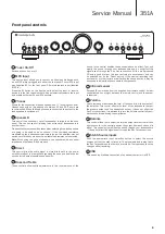
351A
Service Manual
7
Connections
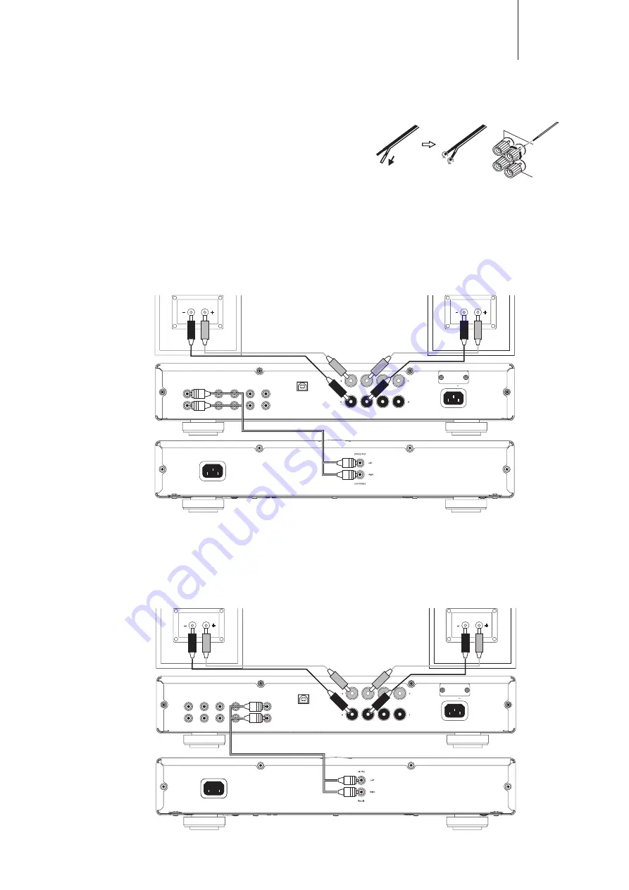
Loudspeakers
Check the impedance of your speakers. When using a pair of speakers,
you can use types with an impedance of between 4 and 8 Ohms.
The red coloured speaker terminals are positive (+) and the black speaker
terminals are negative (-). Make sure correct polarity is maintained at
each speaker connector or the sound can become weak and “phasey”
with little bass.
Using bare wire connections
Prepare the speaker cords for connection by stripping off approximately
10mm (3/8”) or less of the outer insulation. More than 10mm could
cause a short circuit. Twist the wires tightly together so there are no
loose ends. Unscrew the speaker terminal, insert the speaker cable,
tighten the terminal and secure the cable.
Record out connection
The diagram below shows how to connect the amplifier to a tape recorder
or other component with a record function. Please note that either of the
record outputs can be used (as they are both the same signal in parallel).
Note: All connections are made using standard loudspeaker cable.
Basic connection
The diagram below shows the basic connection of your unit to a CD
player and a pair of loudspeakers.
Right
Left
Right
Left
B
A
Right
Left
Right
Left
B
A
Rec Out
S5
S4
S3
S2
S1
Rec Ou
t
S5
S4
S3
S2
S1
Right
Left
USB Audio In
Right
Left
Loudspeaker Terminals
Power AC
Mains Voltage
Selector Switch:
115V/220-230V
AC~50/60Hz
Right
speaker
Amplifier
CD player
Left
speaker
Right
Left
Right
Left
B
A
Right
Left
Right
Left
B
A
Rec Out
S5
S4
S3
S2
S1
Rec Ou
t
S5
S4
S3
S2
S1
Right
Left
USB Audio In
Right
Left
Loudspeaker Terminals
Power AC
Mains Voltage
Selector Switch:
115V/220-230V
AC~50/60Hz
Right
speaker
Amplifier
Tape/MD player
left
speaker
Black
Black
Black
Black
Red
Red
Red
Red
Summary of Contents for AZUR 351A
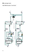
Page 16: ...16 Main PCB Gerbers ...
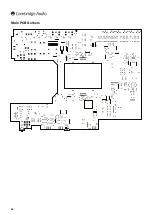
Page 17: ...351A Service Manual 17 Main PCB Gerbers ...
Page 18: ...18 Main PCB Gerbers ...


