540R
AV receiver
azur 540R AV receiver
3
IMPORTANT SAFETY INSTRUCTIONS
Read a
and ffollow iinstructions - All the safety and operation instructions
should be read before use.
Retain iinstructions - These instructions should be retained for future
reference.
Heed w
warnings - Comply with all warnings on the 540R and in the
manual.
Cleaning - Unplug the 540R from the wall outlet before cleaning. Do not
use liquid cleaners or aerosol cleaners. Use a damp cloth for cleaning.
Grounding a
and p
polarisation - The 540R may be equipped with a
polarised alternating current line plug (a plug having one blade wider
than the other). This plug will fit into the power outlet only one way. This
is a safety feature. If you are unable to insert the plug fully into the
outlet, try reversing the plug. If the plug should still fail to fit, contact your
electrician to replace your obsolete outlet. Do not defeat the safety
purpose of the polarised plug. (North America Only)
Overloading - Do not overload wall outlets or extension cord as this can
result in a risk of fire or electric shock. Overloaded AC outlets, extension
cords, frayed power cords, damaged or cracked wire insulation, and
broken plugs are dangerous. They may result in a shock or fire hazard.
Power s
sources - The 540R should be operated only from the type of
power source indicated on the marking label. If you are not sure of the
type of power-supply to your home, consult your product dealer or local
Power Company.
Accessories - Do not place the 540R on an unstable
surface or shelf. The amp may fall, causing serious
injury to a child or adult as well as serious damage
to the product.
Outdoor a
antenna g
grounding - If an outside antenna or cable system is
connected to the product, be sure the antenna or cable system is
grounded so as to provide some protection against voltage surges and
built-up static charges. Section 810 of the National Electrical Code,
ANSI/NIPA No. 70-1984 (section 54 of Canadian Electrical Code, Part 1)
provides information with respect to proper grounding of the mast and
supporting structure, grounding of the lead-in wire to an antenna-
discharge unit, size of grounding conductors, location of antenna-
discharge unit, connection to grounding electrodes, and requirements
for the grounding electrode.
Power c
cord p
protection - Your power supply cord should be placed so that
the power lead is not likely to be walked on or pinched by items placed
upon or against them, paying particular attention to cords at Wall plugs
and where the power lead exits from the 540R.
Contact tthe s
service d
department s
should a
any o
of tthese c
conditions o
occur:
When the power-supply cord or plug is damaged.
If liquid has been spilled, or objects have fallen into the amp.
If the 540R has been exposed to rain or water.
If the 540R does not operate normally after following the operation
instructions, adjust only those controls that are covered by the operation
instructions.
If the amp has been dropped or damaged in any way.
When the amp exhibits a distinct negative change in performance.
Servicing - Do not attempt to service the 540R yourself as removing
cover may expose you to dangerous voltages or other hazards. Refer all
servicing through your dealer to qualified service personnel.
Attachments - Do not use attachments not recommended by your dealer
as they may cause harm to the 540R.
Lightning - For added protection during a thunderstorm, or when it is left
unattended and unused for long period of time, unplug the 540R from
the wall outlet and disconnect the antenna or cable system. This will
prevent damage to the 540R from lightning and power-line surges.
Heat d
dispersion - Leave at least 10 cm of space between the top, back
and sides of the 540R and the wall or other components for proper
ventilation.
Notes o
on u
use
Avoid high temperatures, allow for sufficient heat dispersion when
installed on a rack.
Handle the power cord carefully. Hold the plug when unplugging the
cord.
Keep the 540R free from moisture, water and dust.
Unplug the power cord when not using the 540R for long periods of time.
Do not obstruct the ventilation holes.
Do not let foreign objects, or liquids to get into the 540R.
Never disassemble or modify the 540R.
IMPORTANT
If tthe 5
540R iis rrun a
at a
a v
very h
high llevel, a
a s
sensor w
will d
detect a
a ttemperature
rise a
and s
show ""PROTECTION O
OVERLOAD" o
on tthe d
display. T
The 5
540R w
will
then g
go iinto s
stand-b
by. IIt c
cannot b
be s
switched o
on a
again u
until tthe
temperature h
has ffallen tto a
a m
more n
normal llevel
Plug ffitting iinstructions ((UK only)
The cord supplied with the 540R is factory fitted with a 13Amp mains
plug fitted with a 13Amp fuse inside. If it is necessary to change the
fuse, it is important that a 13Amp one is used. If the plug needs to be
changed because it is not suitable for your socket, or becomes
damaged, it should be cut off and an appropriate plug fitted following
the wiring instructions below. The plug must then be disposed of safely,
as insertion into a 13Amp socket is likely to cause an electrical hazard.
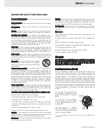
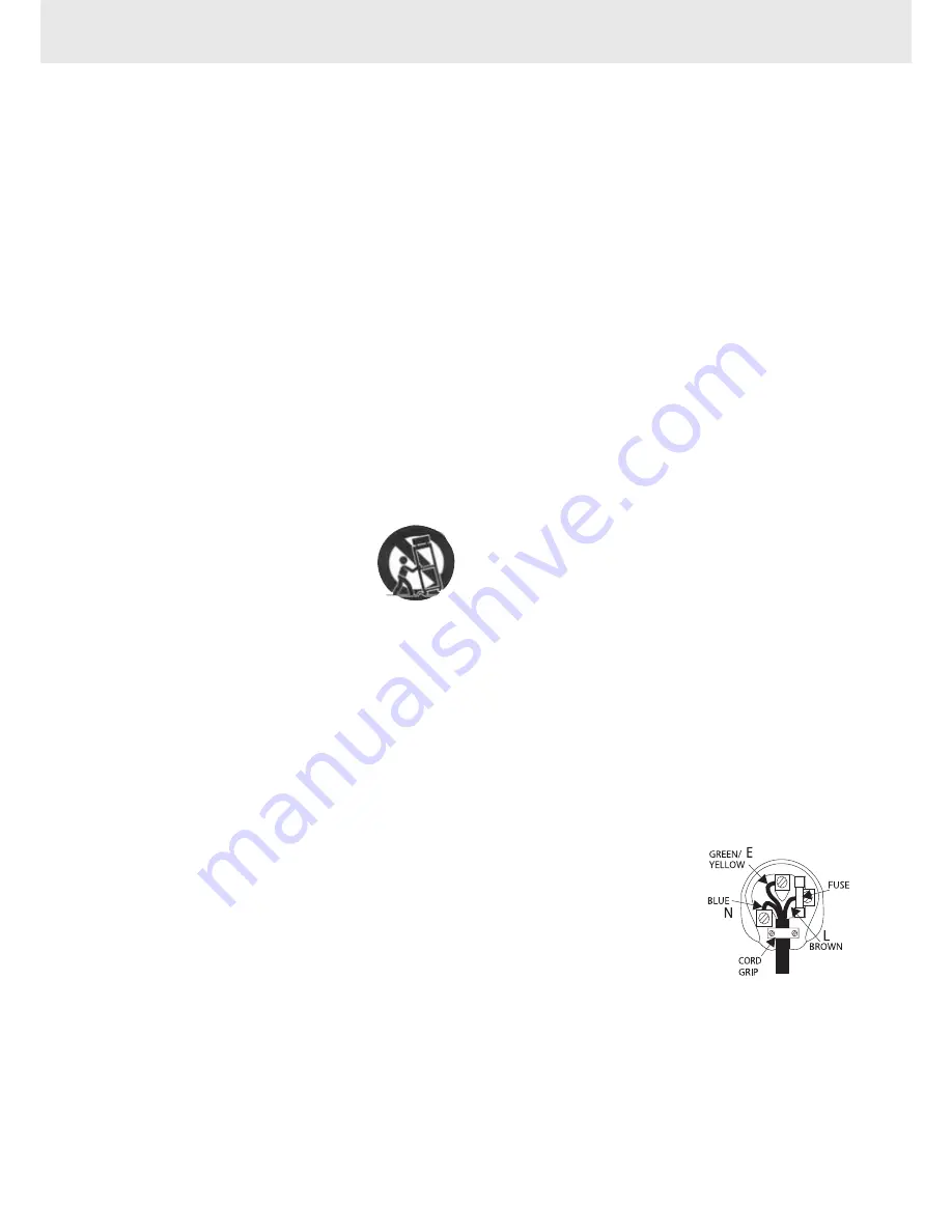
Should it be necessary to fit a 3-pin BS mains plug to the power cord the
wires should be fitted as shown in this diagram. The colours of the wires
in the mains lead of the 540R may not correspond with the coloured
markings identifying the terminals in your plug. Connect them as
follows:-
The wire which is coloured BLUE must
be connected to the terminal which is
marked with the letter 'N' or coloured
BLACK.
The wire which is coloured BROWN
must be connected to the terminal
which is marked with the letter 'L' or
coloured RED
The wire which is coloured
GREEN/YELLOW must be connected to
the terminal which is marked with the
letter 'E' or coloured GREEN.
If your model does not have an earth wire, then disregard this
instruction.


