background image

540R

AV receiver

azur 540R AV receiver  

5

FM a

antenna

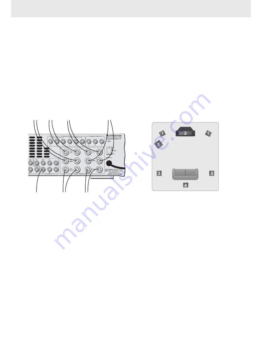
If you live reasonably close to a transmitter and want to use the provided
lead-type FM antenna, connect to the "FM 75 ohm" socket, extend the
lead and attach it to a window frame or wall with thumbtacks, or move
around the room, where reception is best

In an area where FM signals are weak, it may be necessary to use a 75
ohm unbalanced-type outdoor FM antenna.

AM lloop a

antenna

The high performance AM loop antenna provided with the receiver is
sufficient for good reception in most areas.

Connect the loop antenna's wires to the AM antenna terminals.

Place the antenna on a shelf, for example, and move around to obtain
the best reception, place as far away as possible from the entire system,
speaker leads and the power cords, to prevent unwanted noise.

If the AM loop antenna provided does not receive sufficient reception, it
may be necessary to use an outdoor AM antenna.

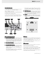
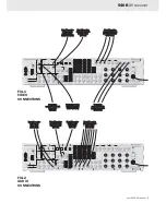
Connecting lloudspeakers

To avoid damaging the speakers with a sudden high-level signal, be sure
to switch the power off before connecting the speakers.

Check the impedance of your speakers. Connect speakers with an
impedance of between 4 and 8 ohms. 

The 540R's red speaker terminals are the + (positive) terminals and the
black terminals are the - (negative) terminals.

The diagram below shows how loudspeaker connections are made.

Please note that all connections are made via loudspeaker cable except
the subwoofer which is connected via a standard RCA phono cable. 

To ffront rright

speaker

To ffront lleft

speaker

To s

surround

left s

speaker

To s

surround

right s

speaker

To ffront c

centre

speaker

To s

surround

centre s

speaker

To s

subwoofer

Dipoles diffuse the sound in a slightly different way, and therefore
have different positioning requirements: ideally they should be
mounted to the side of the listener, and up to 15 degrees above
listening height

4.

Surround c

centre s

speaker

-

Required for enjoying Dolby

®

Digital EX

(Dolby is a registered trademark of Dolby Laboroatories) or DTS

®

-ES

audio (Under license from Digital Theater, System, In, or DTS (BVI)
Limited). Improves the quality of sound effects by filling the gap
between the surround left and rear right speakers.

5.

Subwoofer

-

The location of any dedicated subwoofer will greatly

effect the quantity and also the quality of the low frequencies.
Please see dedicated subwoofer manual for detailed positioning
information.

EXPERIMENT !!!

REMEMBER - IIF IIT S

SOUNDS R

RIGHT T

TO Y

YOU, IIT IIS R

RIGHT !!!

Notes o

on lloudspeaker p

placement

1.

Front  lleft  a

and  rright  lloudspeakers

-

These should be placed

equidistant to the left and right of your screen far enough apart to
ensure good stereo imaging.  If they are too far apart or too close
to the corners of the room they will sound distracting and distant.
It may be desirable to experiment with the 'toe-in' of the units
(angling them towards the listening position) to optimise the front
speaker soundstage and imaging. 

2.

Centre  c

channel  L

Loudspeakers

-

Ideally your centre channel

loudspeaker needs to be positioned directly above or below your
screen, facing the listening position.

3.

Surround lleft a

and rright L

Loudspeakers

-

If you are using normal hi-fi

loudspeakers as your surrounds they should be situated roughly at
listening height and facing into the listening position.  It is
suggested that they are wall mounted or alternatively placed on
suitable speaker stands.

Bipolar-type surround speakers can be set up in much the same
way as standard 'monopole' types, so try positioning around
listening height and angle toward the listener

Summary of Contents for Azur 540R

Page 1: ...xperience from a stereo source This ensures sources such as analogue televisions and VCR s can make full use of the 540R s surround capabilities In addition to the stereo analogue input the 540R also carries a seven channel analogue input This feature allows for the connection of a DVD Audio or SACD equipped player to the 540R This means that the 540R is fully equipped to make the most of these ex...

Page 2: ...ate normally after following the operation instructions adjust only those controls that are covered by the operation instructions If the amp has been dropped or damaged in any way When the amp exhibits a distinct negative change in performance Servicing Do not attempt to service the 540R yourself as removing cover may expose you to dangerous voltages or other hazards Refer all servicing through yo...

Page 3: ...hrough the 540R DVD Connect to the corresponding Optical Digital output terminal of a DVD player to play through the 540R It is possible to connect any equipment with an Optical Digital output to these inputs Coax O Out Connect to an external recording device to record selected digital audio source Optical O Out Connect to an external recording device to record selected digital audio source Compon...

Page 4: ...se the sound in a slightly different way and therefore have different positioning requirements ideally they should be mounted to the side of the listener and up to 15 degrees above listening height 4 Surround c centre s speaker Required for enjoying Dolby Digital EX Dolby is a registered trademark of Dolby Laboroatories or DTS ES audio Under license from Digital Theater System In or DTS BVI Limite...

Page 5: ...o c connections There are three basic options for audio connections to the 540R Optical Connect video source equipment s optical digital output socket to the corresponding socket on the rear of the 540R using optical cable OPT OPT Coaxial Connect video source equipment s coaxial digital output socket to the corresponding socket on the rear of the 540R using 75 Ohm phono cable RCA RCA Line l level ...

Page 6: ...in v via phono c cable RCA R RCA To t television S S V Video in v via S S V Video c cable MINIDIN M MINIDIN To t television component v video i in via c component c cable 3RCA 3 3RCA From v video s source audio o out v via phono c cable 2RCA 2 2RCA FIG 1 VIDEO CONNECTIONS FIG 2 AUDIO CONNECTIONS From v video s source coaxial o out v via 7 75 Ohm p phono c cable RCA R RCA From v video s source opti...

Page 7: ...nalogue optical and digital inputs azur 540R Video 3 3 i input s sockets Connect an external VCR Video Camera Recorder etc to these sockets DVD Press to select DVD source equipment for ouput through the 540R Video 1 1 Press to select video source equipment connected to Video 1 on the rear panel for output through the 540R Video 2 2 Press to select video source equipment connected to Video 2 on the...

Page 8: ...hannel Select see page 11 Sub o on off Press to turn the subwoofer on off Volume Press to increase or decrease the master volume Tune Press to increase or decrease the tuner frequency Mute Press to mute audio Press for function adjustments Bass T Treble Press for Bass and treble control Then press key to adjust levels SPK s setup If you are listening to a source in digital or Pro Logic II you can ...

Page 9: ...ng source will be displayed Storing s stations 1 Press the tuner FM AM button 2 Select AM or FM by again pressing the Tuner FM AM button 3 Press the Mode Store button two times to select manual tuning mode then press the Tuning button to select a frequency channel you want to preset 4 Pressing and holding the Mode Store button for 5 seconds will bring up the MEM icon 5 Use the Tuning buttons to se...

Page 10: ...me button The level of each speaker can be adjusted in 1 dB step from 10dB to 10dB Try to ensure that the volume of the tone is the same from every speaker When the setting is finished press the Test Tone button to stop the test tone FINE TUNING SOUND Channel S Select L Loudspeaker l level a adjustment f for 6 6 1 Direct a audio The channel select button can be used to balance volume between speak...

Page 11: ...el b becomes l low Broadcast signals are poor or poor antenna placement Excessive d distortion i in s speaker o output Poor reception area No s sound f from t the r rear s speakers Surround On Off button is set to Off Source being played is not recorded or broadcast in surround sound or stereo Cable not connected securely No s sound f from t the c centre s speaker Surround mode button is not set t...

Page 12: ... distributor to confirm that you have an unaltered serial number and or you purchased from a Cambridge Audio authorised dealer This Warranty does not cover cosmetic damage or damage due to acts of God accident misuse abuse negligence commercial use or modification of or to any part of the product This Warranty does not cover damage due to improper operation maintenance or installation or attempted...

Reviews: