background image


Gallery Court  Hankey Place  London  SE1 4BB  UK    

Tel: +44 (0)20 7940 2200  Fax: +44 (0)20 7940 2233 

550A/650A 

Issue Date: 10

th

 June 2009 

________________________________________________________________________ 


SERVICE MANUAL


________________________________________________________________________ 


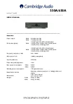
550A/650A 
 

Power output:                             550A 
                                                   650A 

60 watts (into 8

75 watts (into 8

THD (unweighted):                     550A 


                                                   650A 

<0.002% @ 1kHz, 80% of rated power 
<0.05% 20Hz - 20kHz, 80% of rated power 
<0.02% 20Hz - 20kHz @ 10W 
 
<0.002% @ 1kHz, 80% of rated power 
<0.03% 20Hz - 20kHz, 80% of rated power 
<0.02% 20Hz - 20kHz @ 10W 

Frequency response (-1dB) 

5Hz - 50kHz 

S/N ratio (ref 1W) 

>92dB (unweighted) 

Input impedances 

47kohms 

Power Amp damping factor 

>100 

Max. power consumption:        550A 
                                                 650A 

500W 
600W 

Standby power consumption 

<1W @ rated mains 

Bass/Treble controls 

Shelving, ultimate boost/cut +/- 7.5dB @ 20Hz and 
20kHz 

Dimensions 

120 x 430 x 350mm 
(4.7 x 16.9 x 13.8”) 

Weight:                                    550A 
                                                650A 

8.0kg (17.6lbs) 
8.4kg (18.5lbs) 


Summary of Contents for AZUR 550A

Page 1: ...THD unweighted 550A 650A 0 002 1kHz 80 of rated power 0 05 20Hz 20kHz 80 of rated power 0 02 20Hz 20kHz 10W 0 002 1kHz 80 of rated power 0 03 20Hz 20kHz 80 of rated power 0 02 20Hz 20kHz 10W Frequency response 1dB 5Hz 50kHz S N ratio ref 1W 92dB unweighted Input impedances 47kohms Power Amp damping factor 100 Max power consumption 550A 650A 500W 600W Standby power consumption 1W rated mains Bass T...

Page 2: ...Speaker PCB Layout________________________________________________________21 Input PCB Schematic_______________________________________________________22 Input PCB Bill of Materials___________________________________________________23 24 Input PCB Layout__________________________________________________________25 Preamp PCB Schematic____________________________________________________ 26 28 Preamp...

Page 3: ...___________________________________________________49 Protection PCB Schematic____________________________________________________ 50 Protection PCB Bill of Materials________________________________________________ 51 Protection PCB Layout________________________________________________________52 Set up Procedure_____________________________________________________________ 53 IC Details___________...

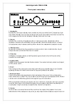
Page 4: ... 5 Speaker LEDs Indicator shows the speaker terminals that are selected The speaker terminals selected are changed with the remote control 6 Direct This control gives the audio signal a more direct path to the power amplifier stage of your amplifier bypassing the bass and treble control circuits for the purest possible sound quality 7 Bass and Treble These controls allow subtle adjustments to the ...

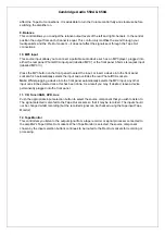
Page 5: ...he front panel socket which automatically selects the input and overrides the rear Phono RCA sockets Note Whilst plugging a device into the front panel automatically selects the MP3 input any other input can still be selected once this has been done As a result you may if desired leave a device permanently plugged into the front panel 11 CD Tuner DAB DVD Aux Push the appropriate input selection bu...

Page 6: ...ray strands of wire are shorting speaker outputs together Please ensure that the loudspeaker terminals have been tightened adequately to provide a good electrical connection It is possible for the sound quality to be affected if the screw terminals are loose The use of A and B speakers affords you an easy and inexpensive way to create a simple multi room system Note When using two pairs of speaker...

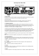
Page 7: ...d recorded signal so that adjustments to the recording parameters of the tape machine can be made Consult the manual of your three head analogue cassette deck for full details 8 Record Out 1 2 These two identical output sockets can be connected to a tape deck or to the analogue Record In sockets on a MiniDisc or CD recorder 9 Aux DVD Tuner DAB CD MP3 These inputs are suitable for any line level so...

Page 8: ...ons The Speaker B connections on the back of the amplifier allow for a second set of speakers to be used i e speakers located in another room The Speaker A B button on the remote control allows the two sets of speakers to be toggled on and off Refer to the Remote Control section of this manual for more information on the Speaker A B operation Set either A or B or both A and B may be selected for u...

Page 9: ... Pre Out sockets are for connecting to the input sockets of a power amplifier such as Cambridge Audio s 840W model or active subwoofer The diagram below shows how to connect the amplifier to an active subwoofer via the Line In inputs on the subwoofer ...

Page 10: ...torms or when unused for long periods of time 14 Refer all servicing to qualified service personnel Servicing is required when the apparatus has been damaged in any way such as the power supply adaptor having been damaged liquid has been spilled or objects have fallen into the apparatus the apparatus has been exposed to rain or moisture does not operate normally or has been dropped WARNING To redu...

Page 11: ... and can radiate radio frequency energy and if not installed and used in accordance with the instructions may cause harmful interference to radio communications However there is no guarantee that interference will not occur in a particular installation If this equipment does cause harmful interference to radio or television reception which can be determined by turning the equipment off and on the ...

Page 12: ...aded AC outlets extension cords frayed power cords damaged or cracked wire insulation and broken plugs are dangerous They may result in a shock or fire hazard Be sure to insert each power cord securely To prevent hum and noise do not bundle the interconnect leads with the power cord or speaker leads Cleaning To clean the unit wipe its case with a dry lint free cloth Do not use any cleaning fluids ...

Page 13: ...550A 650A Exploded Diagram ...

Page 14: ...Y1482 3200 073324E000 TOROID TR 115VAC 60Hz TI 073324 NORATEL FOR 650A 2 PY1597 9465 015000E041 Azur 550A 650A F P CONTROL BOARD ASSY TWO BOARDS 4 PY1598 9465 015000E231 Azur 550A 650A Preamp MCU BOARD ASSY REV A 3 PY1599 9465 015000E311 Azur 550A 650A VOLUME BOARD ASSY REV A 6 PY1600 9455 015000E091 Azur 550A AMP BOARD ASSY REV A 6 PY1601 9465 015000E091 Azur 650A AMP BOARD ASSY REV A not shown P...

Page 15: ...6 4 5 0 4 7 5 0 4 5 0 4 6 1 6 6 8 6 8 8 7 4 7 A 9 6 6 4 8 6 5 0 4 6 9 5 0 4 5 0 4 5 0 4 5 0 4 8 5 0 4 5 70 4 7 5 70 4 0 1 6 0 1 6 0 1 6 6 5 0 4 5 70 4 5 70 4 0 8 1 6 0 6 1 6 0 1 6 6 6 0 6 0 6 6 8 6 B 8 0 6 0 7 6 7 7 6 5 8 C 5 6 6 0 6 8 8 0 6 8 7 7 0 Cambridge Audio 550A 650A Front Panel PCB Schematic ...

Page 16: ...06 9 100nF 50V Mono Ceramic 2 C2 C3 10 5mm Pitch 1100 104043 000 10 10uF 16V Electrolytic 1 C1 20 5 2mm Diameter 1102 100014 000 Lay Flat DIODES 15 Blue Azur LED 3mm 9 D2 D10 HFB963M 130 3100 000030 003 16 Red LED 3mm 1 D11 INTEGRATED CIRCUITS 17 36KHz IR Receiver 1 U1 TSOP34836 Through Hole 3001 348360 000 PY755 18 M74HC4094B 8 Bit Shift Register 1 U2 M74HC4094B1R DIL16 4174 409052 600 PY524 SWIT...

Page 17: ...Cambridge Audio 550A 650A Front Panel PCB Layout ...

Page 18: ... 6 6 8 6 8 6 6 5 0 4 6 72 5 6 72 5 5 0 4 6 5 0 4 6 4 6 4 8 5 70 4 6 6 6 6 6 7 8 81 A 3 1 4 6 8 8 6 4 8 6 5 0 4 7 5 0 4 1B 2 6 2 6 C 5 70 4 D 6 E 4 4 F F D 4 E D 4 E 5 70 4 5 70 4 5 70 4 5 70 4 6 8 7 1 0 6 0 8 0 0 7 0 0 1 0 1 0 6 6 6 6 6 8 7 0 6 18 0 6 6 Cambridge Audio 550A 650A Speaker PCB Schematic ...

Page 19: ... 5 70 4 6 6 6 6 4 5 70 4 7 5 70 4 5 70 4 5 70 4 5 70 4 5 70 4 F 7 F F F 1 0 6 6 16 0 0 E 6 5 7 0 0 0 G G 0 0 86 E 6 5 7 0 0 0 G G 0 0 86 E 6 5 7 0 0 0 G G 0 0 E 6 5 7 0 0 0 G G 0 0 6 E 6 5 7 0 0 G 0 6 0 0 8 E 6 5 7 0 0 G 0 8 0 7 E G E G Cambridge Audio 550A 650A Speaker PCB Schematic ...

Page 20: ...ic 4 C2 C3 C6 C14 10 5mm Pitch 1100 104043 000 18 10uF 16V Electrolytic 1 C7 20 5 2mm Diameter 1102 100014 000 DIODES 23 3mm Red LED IR Demodulator 1 D1 MV50640 IR Housing AP17339 3 24 400V 1A Rectifier 6 D2 D3 D7 D10 1N4004 DO41 1401 140040 000 25 75V 150mA Signal Diode 2 D5 D6 1N4148 D035 1401 141480 000 INDUCTORS 26 24 5T 0 9mm Output Inductor 2 L1 L2 CS79 874967 Through Hole 3203 874801 000 AP...

Page 21: ...Cambridge Audio 550A 650A Speaker PCB Layout ...

Page 22: ...10mm Pitch LK42 24 AWG 10mm Pitch LK48 24 AWG 10mm Pitch J5 G N D L in k s o n u n d e r s id e AUX R CD R DAB R DVD R MD R TM R AUX R CD R DAB R DVD R MD R TM R AUX L CD L DAB L DVD L MD L TM L AUX L CD L DAB L DVD L MD L TM L R7 1 4W Metal Film 470k R6 470k 1 4W Metal Film Clk Dat Strb C66 NP Electrolytic 47uF 16V C46 NP Electrolytic 47uF 16V C44 NP Electrolytic 47uF 16V C42 NP Electrolytic 47uF...

Page 23: ...yester 21 C2 C3 C6 C7 C22 C23 C25 C29 C31 C35 C36 C57 C64 C75 C76 10 5mm Pitch Box 1117 473053E000 17 100nF 50V Mono Ceramic 3 C8 C9 C34 10 5mm Pitch 1100 104043 000 18 100nF 250V Met Polyester 5 C15 C17 C19 C20 CMEB104M250Rxxxx 20 5mm Pitch Box 19 100nF 100V Mono Ceramic 1 C18 10 5mm Pitch 20 1uF 50V Electrolytic 1 C12 20 5mm Dia 1102 107044 000 21 47uF 16V Electrolytic 1 C10 20 5mm Dia 1102 4700...

Page 24: ... CIRCUITS 36 15V 1A Regulator 1 U1 7915 Through Hole 4179 150302 600 37 15V 1A Regulator 1 U2 7815 Through Hole 4178 150302E600 38 5V 1A Regulator 1 U3 7805 Through Hole 4178 050334 700 39 Dual Audio Op Amp 7 U4 U7 U12 NE5532P DIL08 4155 320052 900 PY108 40 16 Way Input Switch 1 U5 TC9163AF SOP28 4191 630103E001 PY470 41 Dual Audio Op Amp 1 U6 RC4580P DIL08 TRANSISTORS 42 45V 500mA PNP Signal 1 Q1...

Page 25: ...Cambridge Audio 550A 650A Input PCB Layout ...

Page 26: ...5V Tone R VOL IN L VOL IN L VOL IN R VOL IN R21 150k 1 4W Metal Film R19 150k 1 4W Metal Film R20 150k 1 4W Metal Film C21 NP Electrolytic 47uF 16V R22 2k2 1 4W Metal Film R23 2k2 1 4W Metal Film R25 2k2 1 4W Metal Film R27 2k2 1 4W Metal Film R33 2k2 1 4W Metal Film R35 2k2 1 4W Metal Film R32 2k2 1 4W Metal Film R34 2k2 1 4W Metal Film R26 4k7 1 4W Metal Film R24 4k7 1 4W Metal Film R28 1k1 1 4W...

Page 27: ... LK4 24 AWG LK3 24 AWG 10mm Pitch LK5 24 AWG 10mm Pitch C2 Met Polyester 47nF 63V LK8 24 AWG 2 3 1 8 4 U3 A NE5532P Audio Op Amp R10 47R 1 4W Metal Film R13 47R 1 4W Metal Film 6 5 7 U3 B NE5532P Audio Op Amp 15V Tone 15V Tone Amp GND Amp GND L POut R POut C37 Met Polyester 47nF 63V C36Met Polyester 47nF 63V LCh HP Out RCh HP Out R8 22k 1 4W Metal Film R66 22k 1 4W Metal Film Amp GND Amp GND C38 N...

Page 28: ...R55 10k 1 4W Metal Film Q2 BC327 25 PNP Signal R54 1 4W Metal Film 10k PIC PIC Clip VI 5V Protect Speaker A Relay Speaker B Relay IR In PIC Short Strobe AC Detect PIC Data Clock Standby Relay DGND 5V D Temp Sense R58 4k7 1 4W Metal Film C69 100nF 50V Mono Ceramic 5V Protect PIC Temp 15V Tone 15V Tone C59 Ceramic 1nF 50V R52 1 8W Metal Film 220R LK51 24 AWG 10mm Pitch 5V PIC IPOD Detect IPOD Detect...

Page 29: ...Pitch 17 10k 1 8W Metal Film 2 R39 R48 1 7 5mm Pitch 18 22k 1 4W Metal Film 2 R8 R66 1 10mm Pitch 19 47k 1 4W Metal Film 2 R11 R12 1 10mm Pitch 20 100k 1 8W Metal Film 4 R42 R45 R47 1 7 5mm Pitch 21 150k 1 4W Metal Film 4 R18 R21 1 10mm Pitch RESISTORS VARIABLE 22 B5k Balance Pot 2 VR1 VR2 VR162G1 B5K L15F Dual 1065 002518E130 PY1240 23 MN20k Balance Pot 1 VR3 VR162G1 MN20K L15F Dual 1062 003518E1...

Page 30: ...ctifier 1 D1 1N4004 DO41 1401 140040 000 INDUCTORS 58 55Z 100MHz Ferrite Bead 4 FB1 FB4 742 70010 FERRITE BEAD INTEGRATED CIRCUITS 59 Dual Audio Op Amp 2 U1 U2 RC4580P DIL08 PY1604 60 Dual Audio Op Amp 4 U3 U6 NE5532P DIL08 4155 320052 900 PY108 61 8 Bit Micro 1 U7 PIC16F882 28 Pin DIL Program with software AP22235 Please add version label 62 Driver Reversible Motor Driver 1 U8 BA6218 Through Hole...

Page 31: ...Cambridge Audio 550A 650A Preamp PCB Layout ...

Page 32: ...6 9 6 9 6 5 70 4 2 8 5 70 4 6 2 89 89 9 6 3 8 6 9 6 3 2 2 692 692 9 2 9 2 9 2 9 2 2 2 8 8 9 4 2 5 70 4 6 5 70 4 5 70 4 8 6 66 4 2 8 9 7 66 8 6 5 70 4 5 70 4 692 692 6 8 7 5 70 4 5 70 4 5 70 4 5 70 4 5 70 4 2 2 6 9 6 9 6 9 8 2 2 6 8 2 0 6 8 7 6 0 7 6 9 4 0 1 0 1 0 1 0 5 A 6 B B B B B 9 4 0 6 5 7 0 0 Cambridge Audio 550A 650A Volume PCB Schematic ...

Page 33: ...STORS VARIABLE 11 50k log ALPS volume pot with motor 1 VR1 RK16812MG082 16mm PY1603 CAPACITORS 12 10pF 50V NP0 Ceramic 2 C1 C14 5 5mm Pitch 5mm Pitch 13 10pF 50V NP0 Ceramic 2 C4 C12 5 2 5mm Pitch 1181 100042 000 14 10nF 50V X7R Ceramic 1 C2 10 1206 15 47nF 63V Met Polyester 4 C5 C6 C9 C10 10 5mm Pitch Box 1117 473053E000 16 100nF 100V Polypropylene 2 C3 C13 CMPA104K100RB07 5 10 7 5mm Pitch Box 11...

Page 34: ...Cambridge Audio 550A 650A Volume PCB Layout ...

Page 35: ...V Electrolytic L Amp Q13 MPSA42 NPN Signal Q12 MPSA42 NPN Signal R19 1k R21 270R R20 47k L Amp3 C5 47uF 16V NP Electrolytic R32 100R 1 4W Metal Film R15 100R 1 4W Metal Film R22 100k Clip In L Clip FB L E S C B D 5 3 1 2 U2 STD03NY NPN Power Tighten to 1 1Nm Form legs to fit into PCB E S C B D 5 1 3 4 U1 STD03PY PNP Power Tighten to 1 1Nm Form legs to fit into PCB 2 CW 3 CCW 1 PR1 Multiturn B200R ...

Page 36: ...F 63V Electrolytic R Amp Q18 MPSA42 NPN Signal Q17 MPSA42 NPN Signal R40 1k R39 270R R41 47k R Amp3 C50 47uF 16V NP Electrolytic R70 100R 1 4W Metal Film R60 100R 1 4W Metal Film R38 100k Clip In R Clip FB R E S C B D 5 3 1 2 U4 STD03NY NPN Power Tighten to 1 1Nm Form legs to fit into PCB E S C B D 5 1 3 4 U3 STD03PY PNP Power Tighten to 1 1Nm Form legs to fit into PCB 2 CW 3 CCW 1 PR2 Multiturn B...

Page 37: ...Stuff Rectifier D15 No Stuff Rectifier D4 200V 3A Rectifier D3 200V 3A Rectifier D2 200V 3A Rectifier D1 200V 3A Rectifier C24 2200uF 50V Electrolytic 105 C25 2200uF 50V Electrolytic 105 C26 2200uF 50V Electrolytic 105 C27 2200uF 50V Electrolytic 105 C42 2200uF 50V Electrolytic 105 C43 2200uF 50V Electrolytic 105 C44 2200uF 50V Electrolytic 105 C41 2200uF 50V Electrolytic 105 L PSU R PSU R1 100R 1...

Page 38: ...on PCB PIC Clip Detect R99 15k 1 8W Metal Film Clip In R R100 15k 1 8W Metal Film Clip FB R LK117 Tinned Link Wire 24AWG R89 15k 1 8W Metal Film Clip In L R90 15k 1 8W Metal Film Clip FB L LK107 Tinned Link Wire 24AWG LK123 Tinned Link Wire 24AWG D11 1N4148 Signal Diode D25 1N4148 Signal Diode D26 1N4148 Signal Diode D27 1N4148 Signal Diode L Amp L Amp R Amp R Amp R Amp R75 1k 1 8W Metal Film R Am...

Page 39: ...m Long 5mm Strip Tin each end 18 AWG Orange Insulated Wire 550A Veiw from underneath CT1 Black Cable Tie CT2 Black Cable Tie CT3 Black Cable Tie CT4 Black Cable Tie CT5 Black Cable Tie CT6 Black Cable Tie CT7 2 5mm x 100mm Black Cable Tie MI1 29x19x0 15mm Mica Washer MI2 29x19x0 15mm Mica Washer MI3 29x19x0 15mm Mica Washer MI4 29x19x0 15mm Mica Washer NS1 M3 3 2x6 4x5 5mm Nylon Spacer NS2 M3 3 2x...

Page 40: ...are not usually stocked by the manufacturer Please obtain these locally 14 2k2 1 8W Metal Film 6 R24 R29 R35 R59 R61 R73 1 7 5mm Pitch 15 3k 1 8W Metal Film 4 R26 R34 R64 R72 1 7 5mm Pitch 16 3k9 1 8W Metal Film 2 R80 R82 1 7 5mm Pitch 17 4k7 1 8W Metal Film 2 R81 R91 1 7 5mm Pitch 18 10k 1 8W Metal Film 2 R7 R52 1 7 5mm Pitch 19 10k 1 4W Metal Film 2 R13 R58 1 10mm Pitch 20 13k 1 8W Metal Film 2 ...

Page 41: ...48 D035 1401 141480 000 Note resistors capacitors and other generic components are not usually stocked by the manufacturer Please obtain these locally 54 No Stuff Rectifier 4 D12 D15 1N5402 DO27 No Stuff 55 400V 1A Rectifier 6 D19 D22 D29 D30 1N4004 DO41 1401 140040 000 56 5V1 1 2W Zener 1 D37 BZX55C5V1 DO35 1402 511201E200 FUSES 57 F8AL Fast Blow Fuse 2 F1 F2 20mm 58 Fuse Holder Base 2 F1 F2 PTF7...

Page 42: ...5 R59 R61 R73 1 7 5mm Pitch 15 3k 1 8W Metal Film 4 R26 R34 R64 R72 1 7 5mm Pitch 16 3k9 1 8W Metal Film 2 R80 R82 1 7 5mm Pitch 17 4k7 1 8W Metal Film 2 R81 R91 1 7 5mm Pitch 18 10k 1 8W Metal Film 2 R7 R52 1 7 5mm Pitch 19 10k 1 4W Metal Film 2 R13 R58 1 10mm Pitch 20 13k 1 8W Metal Film 2 R14 R44 1 7 5mm Pitch 21 15k 1 8W Metal Film 4 R89 R90 R99 R100 1 7 5mm Pitch 22 22k 1 8W Metal Film 2 R12 ...

Page 43: ...A 2mm Pitch No Stuff 49 4 Way Straight Header 1 CN6 B4B XH A 2 5mm Pitch 2300 004100 004 50 3 Way Straight Header 1 CN7 B3P VH 3 96mm Pitch 2300 003400 001 650A Only 51 3 Way Straight Header 1 CN9 B3P VH 3 96mm Pitch 2300 003400 001 DIODES 52 200V 3A Rectifier 8 D1 D4 D12 D15 1N5402 DO27 1401 154020 000 Raise off PCB 53 75V 150mA Signal Diode 14 D5 D11 D18 D25 D28 D31 D32 1N4148 D035 1401 141480 0...

Page 44: ...Cambridge Audio 550A 650A AMP Layout ...

Page 45: ...C 64 4 0 0 D 9 2 1 E E 4 1 C 84 4 0 0 D 9 9 88 68 7 9 4 8 F 4 8 F 8 4 8 F 6 7 4 8 F 0 4 4 0 5 1 5 0 4 4 4 4 4 B B 4 2 4 4 4 4 4 B B 4 2 0 4 4 828 2 B B 0 4 4 828 2 B B 0 4 1 0 0 0 4 1 0 0 D 0 0 7 0 B B D 8B B B C 8B B 7 0 5 0 4 4 D 0 0 0 0 0 7 0 B B D 8B B 5 7 0 0 0 0 7 0 B B D 8B B 5 7 0 0 C 8 A C 8 A Cambridge Audio 550A 650A EU 230V Mains PCB Schematic ...

Page 46: ...N4004 DO41 1401 140040 000 FUSES 9 30VDC 1 1A Polyfuse 3 F1 F3 5mm Pitch 4030 301100 001 10 T6 3AL Slow Blow Fuse 1 FU5 20mm 4030 632500 000 11 Fuse Holder Base 1 FU5 PTF78 or equivalent 20mm Pitch 4031 780000E000 alt Camden YN 4031 140000E000 12 Fuse Holder Cover 1 FU5 PTF78 or equivalent 20mm Pitch 4034 780000E000 alt Camden YN 4034 140000E000 INDUCTORS 13 Standby Transformer Standby Transformer...

Page 47: ...5 C 64 4 0 0 D 9 2 1 E E 4 1 C 84 4 0 0 D 9 9 88 68 7 89 4 8 F 4 8 F 8 4 8 F 6 7 4 8 F 0 4 4 0 5 1 5 0 4 4 4 4 4 B B 4 2 4 4 4 4 4 B B 4 2 0 4 4 828 2 B B 0 4 4 828 2 B B 0 4 1 0 0 0 4 1 0 0 D 0 0 7 0 B B D 8B B B C 8B B 7 0 5 0 4 4 D 0 0 0 0 0 7 0 B B D 8B B 5 7 0 0 0 0 7 0 B B D 8B B 5 7 0 0 C 8 A C 8 A Cambridge Audio 550A 650A 115V Mains PCB Schematic ...

Page 48: ... Camden YN 4034 140000E000 INDUCTORS 13 Standby Transformer Standby Transformer 1 L1 Wah Hing T08707B PCB Mount Use correct 115V type for CU RELAY 14 5V 8A 2P2T Relay 1 RL1 Massuse ME11 005 2Z4 Through Hole TRANSISTORS 15 30V 500mA NPN Darlington 1 Q3 On Semi MPSA14 TO92 1300 140000 100 WIRE TERMINALS 16 Pressed Eyelet 7 J5 J7 J11 J13 J15 MISCELLANEOUS 17 M4 Earth Tag 1 CP1 To be crimped to the Ea...

Page 49: ...Cambridge Audio 550A 650A Mains PCB Layout ...

Page 50: ...M 0805 Thick Film R88 1M 0805 Thick Film R85 1M 0805 Thick Film R84 1M 0805 Thick Film R92 100k 0805 Thick Film R94 100k 0805 Thick Film R97 100k 0805 Thick Film R95 4k7 0805 Thick Film R96 4k7 0805 Thick Film R98 100k 0805 Thick Film R106 100k 0805 Thick Film R116 4k7 0805 Thick Film R122 4k7 0805 Thick Film R130 100k 0805 Thick Film C74 10nF 50V 0805 COG C73 10nF 50V 0805 COG C72 10nF 50V 0805 C...

Page 51: ...P23892 2 2mm Pitch Solder Cable assembly into CN3 footprint 11 8 Way Right Angle Pin Header 1 CN8 NS Tech 201R 1 8P F 2370 008110E000 Solder to CN8 on Protection PCB DIODES 12 75V 0 215A Signal Diode SM 2 D16 D17 BAV99 SOT23 INTEGRATED CIRCUITS 13 Dual Dual Audio Op Amp 1 U5 TI NE5532D SOIC08 Solder on copper side of Protection PCB 14 Low Offset Dual Comparator 1 U6 ST LM393D SO8 Solder on copper ...

Page 52: ...Cambridge Audio 550A 650A Protection PCB Layout ...

Page 53: ...ge Audio 550A 650A Set up Procedure When replacing the STD03NY and STD03PY U1 U4 output devices adjust PR1 PR2 to achieve 13mV 1mV DC with no signal applied measured across each of the 0 22R emitter resistors ...

Page 54: ...IC Pin Layouts for the Cambridge Audio Azur 550A 650A Amplifier Input PCB BC327 Q1 NE5532 U4 U7 U8 U9 U10 U11 U12 7915 U1 7805 U3 7815 U2 ...

Page 55: ...IC Pin Layouts for the Cambridge Audio Azur 550A 650A Amplifier TC9163AF U5 RC4580P U6 Preamp PCB BC327 Q2 BC337 Q3 NE5532 U3 U4 U5 U6 ...

Page 56: ...IC Pin Layouts for the Cambridge Audio Azur 550A 650A Amplifier RC4580P U1 U2 PIC16F882 U7 BA6218 U8 Power Amp PCB 2SC2240GR Q1 Q6 Q7 Q9 Q10 Q15 Q19 Q20 Q23 Q24 Q26 Q32 ...

Page 57: ...outs for the Cambridge Audio Azur 550A 650A Amplifier MPSA92 Q3 Q8 Q25 Q28 Q29 650A ONLY Q30 Q34 Q35 Q36 Q38 Q41 Q46 2SA970GR Q2 Q4 Q5 Q11 Q14 Q16 Q21 Q22 Q27 Q29 MPSA42 Q12 Q13 Q17 Q18 Q31 Q37 Q40 STD03PY U1 U3 ...

Page 58: ...IC Pin Layouts for the Cambridge Audio Azur 550A 650A Amplifier STD03NY U2 U4 Mains PCB MPSA14 Q3 Front Panel PCB BC337 Q1 M74HC4094B1R U2 ...

Page 59: ...IC Pin Layouts for the Cambridge Audio Azur 550A 650A Amplifier TSOP34836 U1 Speaker PCB BC337 Q1 BC327 Q4 CD4011BE U1 OP4N25 U2 TSOP34836 U3 ...

Page 60: ...IC Pin Layouts for the Cambridge Audio Azur 550A 650A Amplifier LM393AP U4 BC337 Q1 MPSA14 Q2 Q3 Volume PCB NE5532D U1 U2 Protection PCB NE5532D U5 ...

Page 61: ...IC Pin Layouts for the Cambridge Audio Azur 550A 650A Amplifier LM393D U6 ...

Reviews: