Cambridge
Audio
550A
&
650A
Safety
Instructions
The exclamation point within an equilateral triangle is intended to alert the user to the presence of important
operating and maintenance instructions in the service literature relevant to this appliance.
WEEE symbol
The crossed-out wheeled bin is the European Union symbol for indicating separate collection for
electrical and electronic equipment. This product contains electrical and electronic equipment which
should be reused, recycled or recovered and should not be disposed of with unsorted regular waste.
Please return the unit or contact the authorised dealer from whom you purchased this product for
more information.
CE mark
This product complies with European Low Voltage (2006/95/EC) and Electromagnetic Compatibility
(89/336/EEC) Directives when used and installed according to this instruction manual. For continued
compliance only Cambridge Audio accessories should be used with this product and servicing must be
referred to qualified service personnel.
C-Tick mark
This product meets the Australian Communications Authority’s Radio communications and EMC
requirements.
Ross Test Stamp
This product meets Russian electronic safety approvals.
FCC regulations
NOTE: THE MANUFACTURER IS NOT RESPONSIBLE FOR ANY RADIO OR TV INTERFERENCE CAUSED
BY UNAUTHORIZED MODIFICATIONS TO THIS EQUIPMENT. SUCH MODIFICATIONS COULD VOID THE
USER AUTHORITY TO OPERATE THE EQUIPMENT.
This equipment has been tested and found to comply with the limits for a Class B digital device,
pursuant to Part 15 of the FCC Rules. These limits are designed to provide reasonable protection
against harmful interference in a residential installation. This equipment generates, uses and can
radiate radio frequency energy and, if not installed and used in accordance with the instructions, may cause
harmful interference to radio communications. However, there is no guarantee that interference will not occur in a
particular installation.
If this equipment does cause harmful interference to radio or television reception, which can be determined by
turning the equipment off and on, the user is encouraged to try to correct the interference by one or more of the
following measures
– Re-orient or relocate the receiving antenna.
– Increase the separation between the equipment and receiver.
– Connect the equipment into an outlet on a circuit different from that to which the receiver is connected
– Consult the dealer or an experienced radio/TV technician for help.
Ventilation
IMPORTANT
– The unit will become hot when in use. Do not place anything on top of the unit. Do not place in an
enclosed area such as a bookcase or in a cabinet without sufficient ventilation.
Ensure that small objects do not fall through any ventilation grille. If this happens, switch off immediately,
disconnect from the mains supply and contact your dealer for advice.
Positioning
Choose the installation location carefully. Avoid placing it in direct sunlight or close to a source of heat. No naked
flame sources, such as lighted candles, should be placed on the unit. Also avoid locations subject to vibration
and excessive dust, cold or moisture. The unit can be used in a moderate climate.
This unit must be installed on a sturdy, level surface. Do not place in a sealed area such as a bookcase or in a
cabinet. Do not place the unit on an unstable surface or shelf. The unit may fall, causing serious injury to a child
or adult as well as serious damage to the product. Do not place other equipment on top of the unit.
Due to stray magnetic fields, turntables or CRT TVs should not be located nearby due to possible interference.
Summary of Contents for AZUR 550A
Page 13: ...550A 650A Exploded Diagram ...
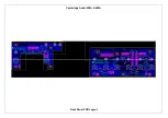
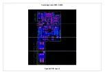
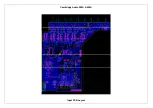
Page 17: ...Cambridge Audio 550A 650A Front Panel PCB Layout ...
Page 21: ...Cambridge Audio 550A 650A Speaker PCB Layout ...
Page 25: ...Cambridge Audio 550A 650A Input PCB Layout ...
Page 31: ...Cambridge Audio 550A 650A Preamp PCB Layout ...
Page 34: ...Cambridge Audio 550A 650A Volume PCB Layout ...
Page 44: ...Cambridge Audio 550A 650A AMP Layout ...
Page 49: ...Cambridge Audio 550A 650A Mains PCB Layout ...
Page 52: ...Cambridge Audio 550A 650A Protection PCB Layout ...
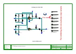
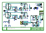
Page 61: ...IC Pin Layouts for the Cambridge Audio Azur 550A 650A Amplifier LM393D U6 ...

