Cambridge
Audio
550A
&
650A
Safety
Instructions
Electronic audio components have a running in period of around a week (if used several hours per day). This will
allow the new components to settle down and the sonic properties will improve over this time.
Power sources
The unit should be operated only from the type of power source indicated on the marking label. If you are not
sure of the type of power-supply to your home, consult your product dealer or local power company.
This unit can be left in Standby mode when not in use and will draw <1W in this state. To turn the unit off, switch
off at the rear panel. If you do not intend to use this unit for a long period of time, unplug it from the mains socket.
Overloading
Do not overload wall outlets or extension cords as this can result in a risk of fire or electric shock. Overloaded AC
outlets, extension cords, frayed power cords, damaged or cracked wire insulation and broken plugs are
dangerous. They may result in a shock or fire hazard.
Be sure to insert each power cord securely. To prevent hum and noise, do not bundle the interconnect leads with
the power cord or speaker leads.
Cleaning
To clean the unit, wipe its case with a dry, lint-free cloth. Do not use any cleaning fluids containing alcohol,
ammonia or abrasives. Do not spray an aerosol at or near the unit.
Battery disposal
Please dispose of any discharged batteries according to local environmental/electronic waste disposal guidelines.
Loudspeakers
Before making any connections to loudspeakers, make sure all power is turned off and only use suitable
interconnects.
Servicing
These units are not user serviceable. Never attempt to repair, disassemble or reconstruct the unit if there seems
to be a problem.
A serious electric shock could result if this precautionary measure is ignored. In the event of a problem or failure,
please contact your dealer.
Summary of Contents for AZUR 550A
Page 13: ...550A 650A Exploded Diagram ...
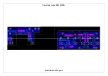
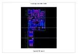
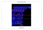
Page 17: ...Cambridge Audio 550A 650A Front Panel PCB Layout ...
Page 21: ...Cambridge Audio 550A 650A Speaker PCB Layout ...
Page 25: ...Cambridge Audio 550A 650A Input PCB Layout ...
Page 31: ...Cambridge Audio 550A 650A Preamp PCB Layout ...
Page 34: ...Cambridge Audio 550A 650A Volume PCB Layout ...
Page 44: ...Cambridge Audio 550A 650A AMP Layout ...
Page 49: ...Cambridge Audio 550A 650A Mains PCB Layout ...
Page 52: ...Cambridge Audio 550A 650A Protection PCB Layout ...
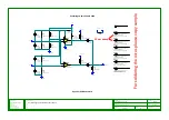
Page 61: ...IC Pin Layouts for the Cambridge Audio Azur 550A 650A Amplifier LM393D U6 ...

