Value
Description/Type
Qty
Component Ident
ManPN
Tolerance
PackageInfo
Factory Part
Number
AP Part Number
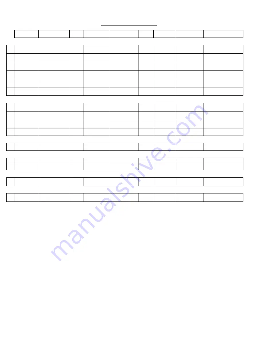
RESISTORS
1
47R
1/4W Metal Film
2
R5, R6
1%
10mm Pitch
2
220R
1/4W Metal Film
7
R7-R12, R14
1%
10mm Pitch
3
10k
1/4W Metal Film
2
R4, R13
1%
10mm Pitch
4
10k
1/8W Metal Film
2
R17, R20
1%
7.5mm Pitch
5
22k
1/4W Metal Film
2
R16, R19
1%
10mm Pitch
6
33k
1/8W Metal Film
2
R18, R21
1%
7.5mm Pitch
CAPACITORS
7
10nF 50V
Ceramic
4
C4, C5, C7, C8
10%
2.5mm Pitch
1100-103043-000
8
10nF 50V
X7R Ceramic
1
C6
10%
1206
9
100nF 50V
Mono Ceramic
2
C2, C3
10%
5mm Pitch
1100-104043-000
10
10uF 16V
Electrolytic
1
C1
20%
5.2mm
Diameter
1102-100014-000
Lay Flat
DIODES
15
Blue Azur LED
3mm
9
D2-D10
HFB963M-130
3100-000030-003
16
Red LED
3mm
1
D11
INTEGRATED CIRCUITS
17
36KHz
IR Receiver
1
U1
TSOP34836
Through Hole
3001-348360-000
PY755
18
M74HC4094B
8 Bit Shift Register
1
U2
M74HC4094B1R
DIL16
4174-409052-600
PY524
SWITCHES
19
Tactile
7
SW1-SW7
KPT-1105A
Through Hole
2400-020200-000
PY043
TRANSISTORS
20
45V 300mA
NPN Signal
1
Q1
BC337-25
TO92
1300-337000-100
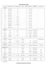
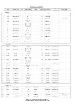
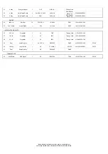
550A/650A Front Panel PCB BOM
Note: resistors, capacitors and other 'generic' components are
not usually stocked by the manufacturer. Please obtain these locally.
Summary of Contents for AZUR 550A
Page 13: ...550A 650A Exploded Diagram ...
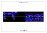
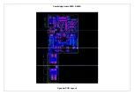
Page 17: ...Cambridge Audio 550A 650A Front Panel PCB Layout ...
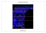
Page 21: ...Cambridge Audio 550A 650A Speaker PCB Layout ...
Page 25: ...Cambridge Audio 550A 650A Input PCB Layout ...
Page 31: ...Cambridge Audio 550A 650A Preamp PCB Layout ...
Page 34: ...Cambridge Audio 550A 650A Volume PCB Layout ...
Page 44: ...Cambridge Audio 550A 650A AMP Layout ...
Page 49: ...Cambridge Audio 550A 650A Mains PCB Layout ...
Page 52: ...Cambridge Audio 550A 650A Protection PCB Layout ...
Page 61: ...IC Pin Layouts for the Cambridge Audio Azur 550A 650A Amplifier LM393D U6 ...


