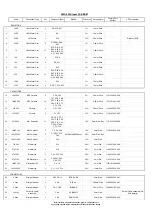
Value
Description/Type
Qty
Component Ident
ManPN
Tolerance
PackageInfo
Factory Part
Number
AP Part Number
RESISTORS
1
4R7
1/4W Metal Film
1
R63
1%
10mm Pitch
2
10R
1/4W Metal Film
2
R14, R15
1%
10mm Pitch
3
10R
1/8W Metal Film
2
R38, R49
1%
7.5mm Pitch
4
22R
1/4W Metal Film
2
R36, R37
1%
10mm Pitch
5
33R
2W Carbon
2
R16, R17
10%
20mm Pitch
Add ferrite beads FB1-4 to
resistor legs for EMC
6
47R
1/4W Metal Film
2
R10, R13
1%
10mm Pitch
7
220R
1/8W Metal Film
1
R52
1%
7.5mm Pitch
8
Wire Link
1/4W Metal Film
1
R64
1%
10mm Pitch
Use 24AWG wire link
9
1k
1/4W Metal Film
5
R1, R3, R5, R6,
R9
1%
10mm Pitch
10
1k
1/8W Metal Film
2
R61, R62
1%
7.5mm Pitch
11
1k1
1/4W Metal Film
4
R28-R31
1%
10mm Pitch
12
1k5
1/8W Metal Film
2
R41, R43
1%
7.5mm Pitch
13
2k2
1/4W Metal Film
8
R22, R23, R25,
R27, R32-R35
1%
10mm Pitch
14
4k7
1/4W Metal Film
7
R2, R4, R24, R26,
R50, R51, R58
1%
10mm Pitch
15
4k7
1/8W Metal Film
2
R40, R44
1%
7.5mm Pitch
16
10k
1/4W Metal Film
9
R7, R53-R57, R59,
R60, R65
1%
10mm Pitch
17
10k
1/8W Metal Film
2
R39, R48
1%
7.5mm Pitch
18
22k
1/4W Metal Film
2
R8, R66
1%
10mm Pitch
19
47k
1/4W Metal Film
2
R11, R12
1%
10mm Pitch
20
100k
1/8W Metal Film
4
R42, R45-R47
1%
7.5mm Pitch
21
150k
1/4W Metal Film
4
R18-R21
1%
10mm Pitch
RESISTORS VARIABLE
22
B5k
Balance Pot
2
VR1, VR2
VR162G1-B5K-L15F
Dual
1065-002518E130
PY1240
23
MN20k
Balance Pot
1
VR3
VR162G1-MN20K-
L15F
Dual
1062-003518E160
CAPACITORS
24
No Stuff
Ceramic
1
C44
2.5mm Pitch
No Stuff
25
10pF 50V
NP0 Ceramic
8
C3, C8, C18, C23,
C28, C33, C48,
C52
5%
2.5mm Pitch
1181-100042-000
26
100pF 50V
NP0 Ceramic
3
C50, C65, C71
5%
2.5mm Pitch
1181-101042-000
27
680pF 50V
NP0 Ceramic
2
C9, C10
5%
2.5mm Pitch
1181-681042-000
28
1nF 50V
Ceramic
1
C11
10%
5mm Pitch
29
1nF 50V
Ceramic
13
C12, C39, C41-
C43, C45, C56,
C58, C59, C63,
C64, C68, C70
10%
2.5mm Pitch
1100-102043-000
30
1.5nF 63V
Polypropylene
2
C29, C30
5%
5mm Pitch Box
1114-152052E000
31
10nF 63V
Polypropylene
2
C22, C34
5%
5mm Pitch Box
32
10nF 50V
Ceramic
3
C40, C66, C67
10%
2.5mm Pitch
1100-103043-000
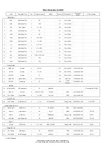
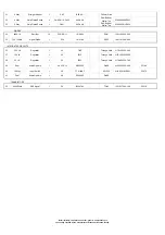
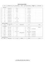
550A 650A Preamp PCB BOM
Note: resistors, capacitors and other 'generic' components are
not usually stocked by the manufacturer. Please obtain these locally.
Summary of Contents for AZUR 550A
Page 13: ...550A 650A Exploded Diagram ...
Page 17: ...Cambridge Audio 550A 650A Front Panel PCB Layout ...
Page 21: ...Cambridge Audio 550A 650A Speaker PCB Layout ...
Page 25: ...Cambridge Audio 550A 650A Input PCB Layout ...
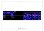
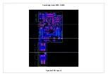
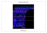
Page 31: ...Cambridge Audio 550A 650A Preamp PCB Layout ...
Page 34: ...Cambridge Audio 550A 650A Volume PCB Layout ...
Page 44: ...Cambridge Audio 550A 650A AMP Layout ...
Page 49: ...Cambridge Audio 550A 650A Mains PCB Layout ...
Page 52: ...Cambridge Audio 550A 650A Protection PCB Layout ...
Page 61: ...IC Pin Layouts for the Cambridge Audio Azur 550A 650A Amplifier LM393D U6 ...


